
How to measure VFD output voltage is a key part of diagnosing motor and drive signals. Consider input vs. output when diagnosing electrical signals in a motor/drive system. To alter motor torque, a variable frequency drive (VFD) converts input mains with constant voltage and frequency into a range of voltage and frequency that may be changed.
What Is the VFD Output Voltage?
A power conversion device can be classified as a variable frequency drive (VFD). It transforms a
conventional power supply with a set voltage and frequency into one that allows for both voltage and frequency adjustment. This makes it possible to regulate the motor’s speed and power.
In essence, the power that the VFD provides to the motor is its output voltage. It has a direct impact on the motor’s torque and speed, making it essential. Higher voltage can result in faster speeds, whereas lower voltage might result in slower speeds. Comprehending this crucial facet of VFDs aids in comprehending their general operation and capabilities.
How to measure VFD output voltage?
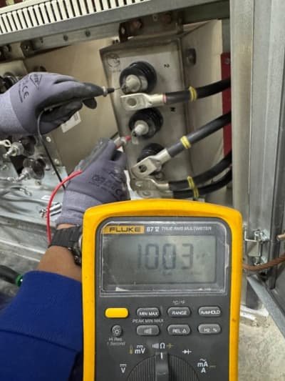
Using a multimeter to test the health of a Variable Frequency Drive (VFD) is a helpful troubleshooting step when identifying possible problems. A VFD regulates the speed of an electric motor by altering the frequency and voltage of the electricity sent to the motor. The VFD should be checked regularly to make sure it is operating properly.
Steps to Measure VFD Output Voltage:
-
Set the multimeter to AC voltage mode.
-
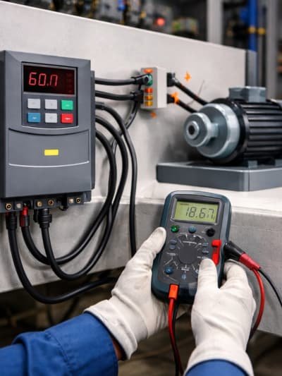
Connect the probes to the VFD output terminals (U–V, V–W, U–W for three-phase, or across the output terminals for single-phase).
-
Power ON the VFD and run the motor at the required speed.
-
Observe the voltage readings shown on the multimeter.
-
Compare the readings with the expected values from the VFD datasheet or parameters.
-
Record and analyze the results for troubleshooting or maintenance.
When Should You Measure the Output Voltage of a VFD?
When commissioning or troubleshooting a Variable Frequency Drive (VFD), it is important to monitor the output voltage to ensure the motor receives the correct power. Here’s how to measure VFD output voltage and when to take measurements:
- Setting up: Measure the output voltage during initial setup to confirm the drive is configured correctly and operating as intended.
- Troubleshooting: Measuring output voltage helps identify issues if the motor isn’t working properly or if the VFD shows error codes. Low or erratic voltage may indicate problems with the motor, power supply, or VFD components.
- Routine Maintenance: Regular measurements help spot issues early, preventing system failures. For LV VFD and MV VFD, periodic voltage checks ensure motors operate efficiently and safely. Our team at R-aletqan provides professional VFD maintenance for both low and medium voltage drives.
Tools Required to Measure VFD Output Voltage
Equipment Needed:
- Make sure the digital multimeter can measure resistance, AC/DC voltage, and diode test functions.
- Personal protective equipment (PPE): Always use safety eyewear, insulated gloves, and other suitable PPE to handle high voltage. The Klein Tools Electrician’s Insulated Gloves are a high-quality PPE option.
Why Standard Multimeters Can Misread VFD Output
Measuring VFD output voltage is tricky because the VFD produces a high-frequency PWM waveform, not a pure sine wave. Standard multimeters may show lower or unstable readings.
For reliable results:
- Use a True RMS meter suitable for PWM signals.
- Consider oscilloscopes for waveform verification if needed.
- Remember long cables and high dv/dt spikes can create voltage peaks at the motor terminals higher than the meter reading.
Always interpret measurements in the context of the waveform, cable length, and VFD settings for accurate troubleshooting.
Safety Precautions Before Taking Measurements
Prioritizing safety before taking any measurements is critical to avoid accidents and ensure accurate results. For anyone learning how to measure VFD output voltage, following these safety steps is essential:
- Evaluate the environment: Check for hazards like loose wires, sharp objects, or uneven surfaces. Control access to the work area and keep the workspace clean and organized.
- Use Personal Protective Equipment (PPE): Wear safety glasses for eye protection and gloves for hand safety. Depending on the site, additional PPE such as helmets or hearing protection may be required.
- Check Measuring Tools: Inspect equipment for cracks, loose parts, or damage. Ensure tools are calibrated, handle them correctly, and avoid errors such as parallax. Reduce vibrations when possible.
- Follow Procedures: Always follow workplace safety rules, take breaks to avoid fatigue, and report unsafe conditions immediately.
Common Mistakes to Avoid While Measuring VFD Output
When measuring VFD output voltage, several common mistakes can lead to inaccurate readings, equipment damage, or reduced lifespan of the drive. Here are the key errors to avoid:
- Improper Wiring: Poor wiring or grounding can harm the motor and VFD. Loose connections may cause arcing, overheating, or IGBT damage. Always follow the manufacturer’s torque specifications.
- Ignoring Harmonic Distortion: Uncontrolled harmonics affect power quality. Use Active Front End (AFE) drives or filters to minimize distortion.
- Insufficient Ventilation and Cooling: Overheating shortens VFD life. Ensure proper airflow, remove dust from heat sinks, and maintain clean cooling paths.
- Other Common Errors:
- Using a mismatched motor (voltage, power, or load not aligned with the VFD).
- Ignoring warning signs such as unusual noises, vibrations, or error codes.
- Allowing moisture near the VFD, which may cause short circuits.
- Damaged or misplaced probes leading to faulty measurements.
- Forgetting measurement tolerances when calculating efficiency.
- By avoiding these mistakes, you can extend the life of your VFD and ensure safe, reliable operation.
Read About: Harmonic distortion in VFD
How to Interpret Output Voltage Readings
To know how to measure VFD output voltage and interpret the results, you must first understand what the measured value means in the context of the circuit or device. Always compare the reading with the expected values from datasheets, schematics, or previous experience.
Steps to Interpret the Readings:
-
-
Calculate the Predicted Voltage – Obtain the expected value from the datasheet, circuit diagram, or similar systems.
-
Measure the Voltage – Use a multimeter or measuring equipment to record the actual value.
-
Compare the Measured Value with the Expected Value: Normal Reading : Within tolerance = system is likely healthy . Low Voltage: May indicate a weak power source, overload, or short circuit. High Voltage: May suggest a faulty regulator, unstable supply, or damaged component.
-
4.Troubleshoot Deviations – Analyze the difference to identify possible causes and plan corrective action.
Troubleshooting Abnormal Output Voltage Values
How to measure VFD output voltage, common reasons, and how to troubleshoot them:
● Problems with Input Voltage:
- Verify input voltage is within rated range.
- Unstable input can cause output variations.
- Wrong polarity may damage components.
● Problems with Loading:
- Overload causes voltage drop – use higher capacity supply if needed.
- Short circuits lower voltage or shut off supply – inspect wiring/load.
- Ensure load impedance matches specifications.
● Issues with the Feedback Circuit:
- Check resistor divider connections.
- Optocoupler faults can affect stability.
- Feedback loop issues may cause variations.
● Failures of Other Components:
- Switching transistor faults affect voltage – test base/collector.
- Bad diodes or capacitors can cause output problems.
● Using a Multimeter:
- Measure input/output voltages.
- Test for shorts across circuits.
- Check continuity/resistance of parts.
● Environmental Elements:
- Extreme temperatures affect performance – ensure cooling.
- High humidity can cause corrosion/shorts – control environment.
● Connections & Wiring:
- Tighten loose connections.
- Replace damaged wires.
- Verify wiring matches schematic.
● Particular Concerns:
- High voltage spikes cause swings/damage.
- High ripple voltage impacts sensitive equipment – check grounding/filtering.
Differences in Output Voltage: Single vs. Three-Phase VFDs
| Type of VFD | Input | Output | Applications / Notes |
|---|---|---|---|
| Single-Phase VFD | AC, single-phase (e.g., 120V or 240V) | Single or three-phase (output typically = input voltage) | Smaller motors, light business, residential, where three-phase is required or unavailable. Limited for high-power applications. |
| Three-Phase VFD | AC, three-phase (e.g., 208V, 240V, 480V) | Three-phase AC | High-power applications, industrial settings, large motors, stable power and better torque control. Can manage higher voltages and demanding loads. |
Need Help Measuring Your VFD Output?
At R-aletqan, we provide professional VFD measurement and troubleshooting services. Using precise tools like multimeters, our skilled team can identify and resolve any issues with your VFDs. Regular checks and accurate measurements help prevent unexpected downtime and extend the life of your equipment. For comprehensive diagnostics, maintenance, and support, our experts ensure your motors and drives operate safely and efficiently, giving you peace of mind in your industrial operations.
FAQ
Do VFDs change voltage?
Variable frequency drives, or VFDs, may alter voltage, yes.
Can you use a regular multimeter to measure VFD voltage?
It is possible to test the voltage on a Variable Frequency Drive (VFD), especially at the input terminals, using a standard multimeter.
Is the VFD output voltage AC or DC?
AC power.