PLC panel earthing is often the hidden reason behind flickering I/O signals, intermittent faults, and noisy analog measurements that frustrate engineers and disrupt industrial operations. In Saudi Arabia’s industrial facilities, PLC panels operate near drives, motors, and switching equipment, exposing control circuits to electrical noise, transient events, and grounding weaknesses.
This article explains what it means, why it is critical, how to verify it during commissioning, and best practices to prevent avoidable faults, with real-world scenarios included to illustrate common defects and solutions.
What Is PLC Panel Earthing in Industrial Automation?
PLC panel earthing refers to how a panel’s metal enclosure, mounting plate, protective earth (PE) conductors, and bonding points are connected to the plant earthing system. Its objective is to provide a low-impedance path for fault currents and to support a stable reference for control and communication circuits.
In practice, improper or incomplete earthing can lead to flickering I/O signals, noisy analog measurements, or intermittent faults, highlighting its critical role in reliable industrial operations.Achieving this low-impedance path requires ensuring paint-free contact points and secure bonding straps.
In most industrial designs, typically includes:
- Protective earthing of the enclosure and metal parts (PE connection)
- Equipotential bonding between the panel, cable trays, and nearby equipment
- Defined earthing points for cable shields (based on OEM guidance and EMC strategy)
- Clear separation between protective earth and signal reference where required
Why Earthing Is Critical in High-Noise Industrial Environments?
Proper earthing supports safety first, and it can also reduce instability that appears as intermittent faults. Earthing is primarily a safety measure. It helps ensure that exposed metal parts do not remain at dangerous potentials in the event of insulation failure. For automation systems, a well-designed earthing and bonding strategy can also reduce susceptibility to electromagnetic interference (EMI) and transient disturbances.
Studies in Saudi Arabia’s industrial sector indicate that up to 25% of intermittent PLC faults and communication issues can be directly linked to inadequate or improperly maintained earthing systems, especially in the hot and dry climates of regions like Riyadh and the Eastern Province.
- Key benefits include:
- Lower nuisance trips and fewer intermittent I/O changes linked to electrical noise.
- Better communication stability for Ethernet-based protocols under industrial load.
- Cleaner troubleshooting conditions by minimizing floating references and unintended return paths.
- Safer maintenance work when isolation and bonding are consistent and documented.
Industry standards for electrical installations and EMC commonly emphasize earthing, bonding, and cable management as part of noise control. The correct implementation should always be checked against your PLC platform and the project’s accepted design.
Symptoms of Poor PLC Panel Earthing
Poor earthing often causes intermittent instability depending on load or switching events. Symptoms that teams typically investigate include:
- Intermittent communication drops, especially during motor starts or VFD switching events.
- Analog signal drift or noisy measurements (e.g., 4–20 mA loops showing fluctuations).
- Digital inputs changing state unexpectedly, or “flickering” signals.
- HMI/SCADA showing sporadic bad-quality tags without a clear network change.
- Repeated module diagnostic events that do not follow a clear wiring defect.
These symptoms can have multiple causes. That is why earthing should be verified using documented tests and not assumed as the root cause without evidence.
Most earthing issues arise from loose connections, floating shields, or undocumented changes during maintenance rather than design faults.
Typical Panel Earthing Issues in Industrial Settings
In industrial facilities, PLC panels are installed in various environments that can affect earthing performance. Recognizing common scenarios helps engineers anticipate potential issues and maintain stable automation. Typical situations include:
- Panels installed near VFD output cables or motors: proximity can introduce electrical noise if proper separation is not maintained.
- Shared earthing points across multiple panels: may create unintended current paths, leading to unstable signals.
- Inconsistent or floating cable shields: shields not properly terminated to earth can allow EMI to interfere with control signals.
- Incomplete bonding of the enclosure or door: paint, insulation, or loose bonds may prevent effective metal-to-metal contact.
- PE conductors added or modified after installation without documentation:can introduce unexpected loops or faults in the panel grounding system.
Understanding these scenarios allows maintenance and commissioning teams to proactively check, document, and correct earthing practices, improving reliability, reducing intermittent faults, and ensuring safe operations.
Read About: PLC not communicating
Step-by-Step Testing Procedure for Safe Operations
Verification of PLC panel earthing should always be safe, repeatable, and well-documented as part of commissioning or routine maintenance.
A practical testing procedure typically includes:
- Visual inspection: Ensure a dedicated PE conductor is connected to the panel earthing point.
- Bonding checks: Verify enclosure, mounting plate, and door bonds are intact and follow approved methods.
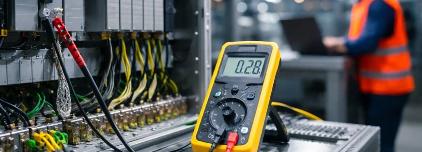
- Continuity measurements: Test continuity between panel metalwork and the plant earth bar/grid using approved instruments.
- Shield termination inspection: Confirm cable shields are terminated consistently, per OEM and EMC guidance.
- Cable routing review: Maintain proper separation between power and control/communication cables.
- Documentation review: Verify earthing drawings, as-built records, and previous inspection logs.
All measurements should be recorded, including the instrument used, calibration status, and test point locations, to support commissioning, maintenance, and future troubleshooting.
Real-World Earthing Defects During Industrial Commissioning
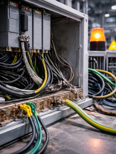
During industrial commissioning, several earthing defects are commonly observed that can affect PLC panel performance and overall system stability. Typical findings include:
- Loose or corroded earthing lugs at the main earth bar, reducing the effectiveness of the protective earth.
- Missing or incomplete door/enclosure bonding, often due to paint or insulation preventing proper metal-to-metal contact.
- Floating or inconsistently terminated cable shields, which can allow EMI to interfere with control and communication signals.
- PE conductors added or modified after initial installation without proper documentation, creating unexpected earth loops.
- Control cables routed too close to VFD outputs or high-current feeders, resulting in interference or signal instability.
- Multiple ad-hoc earth points installed during maintenance without recording the changes, complicating troubleshooting.
Most earthing problems are not due to design issues, but result from execution or maintenance practices such as loose connections, inconsistent shield terminations, or undocumented modifications.
Read about: PLC Fault Finding Techniques
Grounding vs Earthing in PLC Systems
Terminology can differ by region, so it is important to clarify what your project means by each term. In many IEC-based contexts, “earthing” refers to connecting exposed conductive parts to earth for safety (protective earthing). In some other contexts, “grounding” is used more broadly to include:
- Protective earthing (PE):primarily for fault current paths and safety.
- Functional earthing / reference: provides a stable reference for measurement signals in certain designs, following OEM guidance.
- Shield grounding / bonding: manages electromagnetic interference and ensures proper cable shield behavior, depending on EMC requirements.
Because these concepts are often mixed in casual discussion, always refer to project terminology, drawings, and OEM manuals for PLCs, network components, and instrumentation. Correct understanding ensures safety, signal stability, and EMC compliance.
Best Practices for Safe and Reliable Industrial Panels
Best practices for PLC panel earthing are most effective when they are consistent, documented, and verified. Proper installation discipline combined with EMC-aware routing and consistent bonding improves system reliability.
Common practices include:
- Use a clearly labeled earthing bar in the panel, connected to the plant earth network.
- Bond the enclosure, mounting plate, and door using approved bonding methods where required.
- Keep shield termination rules consistent across the project and document them.
- Route power and signal cables separately, avoiding parallel runs with VFD output cables where possible.
- Use industrial communication components suited for plant conditions and document network settings.
- Apply change control: do not modify earthing or shielding without documentation and approval.
If PLC panels interface with VFDs and motors, coordinate earthing checks with the drive manufacturer’s wiring guidance, because switching behavior can increase sensitivity to poor routing and bonding.
Standards & Inspection Requirements for Panel Earthing
PLC panel earthing must comply with relevant industrial standards to ensure safety, system stability, and EMC compliance. During commissioning and audits, verification should follow both project specifications and recognized standards.
Commonly referenced standards include:
- IEC 60364– Low-voltage electrical installations.
- IEC 61000 series – Electromagnetic compatibility (EMC).
- IEC 61131-2– Equipment requirements for programmable controllers.
- IEC 62305 – Lightning protection, if surge coordination and lightning risk are part of the scope.
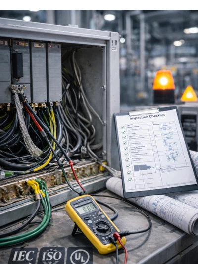
During inspection and commissioning, earthing verification typically involves:
- Panel and cable inspections to confirm proper connections.
- Loop checks for instrumentation circuits.
- Network readiness tests for PLC communication lines.
- Documentation review of drawings and as-built records to ensure compliance.
Recording results in signed checklists provides evidence for commissioning acceptance and future maintenance reference.
Facing Problems with Your Industrial Panels?
Support is most valuable when it delivers clear evidence and a practical corrective plan. If your site is experiencing intermittent faults, communication instability, or repeated I/O noise symptoms, it can be practical to review earthing and bonding as part of a broader diagnostic scope. Riyadh Al-Itqan Company (R-Aletqan) supports industrial clients with PLC systems and automation integration where earthing quality, documentation, and commissioning discipline matter.
Conclusion
A strong earthing strategy reduces avoidable faults and supports safer, more predictable commissioning. PLC panel earthing should be treated as a documented engineering topic, not a last-minute check. When earthing is verified through inspections and recorded tests, teams troubleshoot faster and reduce the chance of repeated intermittent issues.
We provide expert solutions in Riyadh, industrial electrical grounding services in Jeddah, EMC bonding and shielding for automation panels in Dammam, and comprehensive earthing system audits for industrial facilities across Saudi Arabia, including major industrial hubs like Jubail and Yanbu. Our team ensures your systems are compliant, safe, and resilient.
FAQ
How do I know if the PLC module is faulty?
Use the platform diagnostic tools to read module status, fault codes, and channel diagnostics. If verified wiring and correct configuration still produce persistent module faults, further OEM-level testing or controlled replacement may be required.
What is the first step in PLC fault finding?
Start by confirming safe conditions and capturing the exact symptom with time and error messages. Then check CPU/module status indicators and verify power stability before making configuration changes.
Can communication issues cause PLC program errors?
Communication issues can cause abnormal data quality, timeouts, or missing inputs that affect program logic and sequences. The correct approach is to document whether the program is reacting to invalid or missing signals rather than assuming a software defect.