Performing a dielectric test for low voltage switchgear is not just a standard commissioning step it is the final verification that an LV assembly can safely withstand real operational electrical stress. For commissioning engineers, QA/QC teams, and panel builders in Saudi Arabia, confusing a power-frequency withstand (hi-pot) test with an insulation resistance (IR) test can lead to serious risks.
While a dielectric test validates insulation strength under high AC stress, an IR test only assesses insulation condition at a much lower DC voltage. Getting this distinction wrong before energization can either mask critical insulation defects or expose sensitive components to unnecessary damage. According to IEC 61439-1 and IEC 61439-2, dielectric testing is a key verification method for confirming insulation performance without breakdown or flashover for assemblies up to 1000 V AC or 1500 V DC.
what is the Dielectric Test for Low Voltage Switchgear?
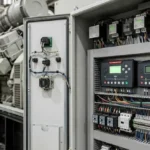
Dielectric Test for Low Voltage Switchgear is a verification test used to ensure that an LV switchgear assembly can withstand a specified high AC voltage without insulation failure. It is commonly known as a hi-pot or power-frequency withstand test and is performed during commissioning to confirm that the insulation system can handle electrical stress safely without breakdown or flashover.
What is the Purpose of the Dielectric Test?
A dielectric test for low voltage switchgear is performed to verify that the insulation system of the assembly can withstand the specified industrial-frequency test voltage without failure. Its main purpose is to confirm that the LV switchgear can safely handle electrical stress higher than normal operating conditions without insulation breakdown or flashover.
Unlike routine measurements, this test provides a direct verification of the insulation’s ability to perform under high AC stress, ensuring the reliability and safety of the assembly before energization in accordance with IEC 61439 requirements.
Dielectric Test vs Insulation Resistance Test
A dielectric withstand test checks whether the assembly insulation system can survive the specified industrial-frequency test voltage for the required duration. In contrast, an insulation-resistance test uses a DC insulation tester to evaluate leakage resistance through the insulation system.
| Feature | Dielectric Test | Insulation Resistance Test |
|---|---|---|
| Type of Voltage | AC High Voltage | DC Low Voltage |
| Purpose | Withstand capability verification | Insulation condition check |
| Test Level | High stress | Low stress |
| Acceptance | No breakdown / flashover | Minimum resistance value |
| Stage | Commissioning | Pre-check / maintenance |
What the standard for Dielectric Test?
A dielectric withstand test is carried out in accordance with IEC 61439-1 and IEC 61439-2, which define the verification requirements for low is -voltage switchgear and controlgear assemblies up to 1000 V AC or 1500 V DC. The test is performed at 50 Hz and is considered valid when the assembly withstands the specified test voltage for the required duration without breakdown or flashover.
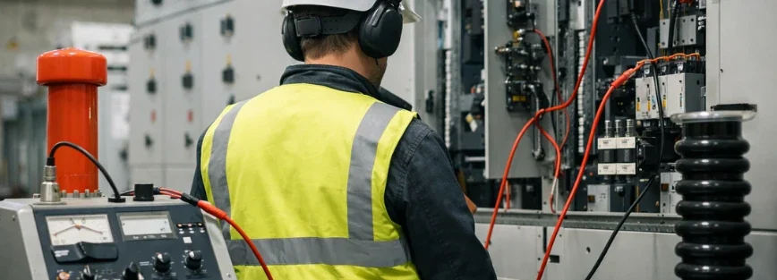
Step-by-Step Procedure with Safety Measures
1) Confirm testing requirement
Before starting, verify whether a dielectric test is required based on IEC 61439 documentation, project specifications, and factory test records. This ensures the test is necessary and not a redundant site repetition.
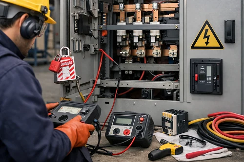
2) Ensure electrical safety (LOTO)
The switchgear must be fully de-energized and isolated using lockout/tagout procedures. All stored energy should be discharged and absence of voltage must be confirmed before testing begins.
3) Inspect and prepare the equipment
The assembly should be checked for cleanliness and dryness. Any presence of dust, moisture, or contamination can affect test results and may cause false failure or damage during high-voltage testing.
4) Isolate sensitive components
Electronic devices such as meters, protection relays, and control electronics that cannot withstand high test voltage must be disconnected or properly protected as per manufacturer recommendations.
5) Apply test voltage correctly
The dielectric test is applied between phases, between phase and earth, and between isolated circuits according to IEC 61439 requirements, ensuring correct test points are selected.
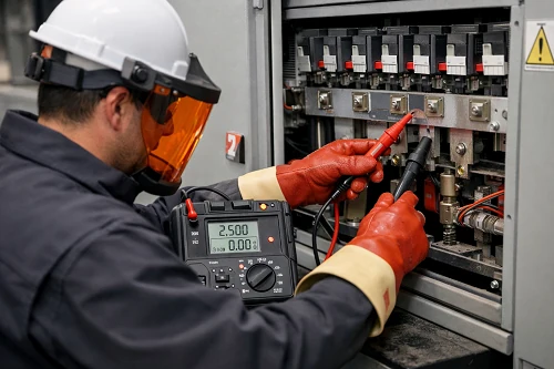
6) Perform the withstand test
Apply the specified AC voltage at 50 Hz for the defined duration (typically 1 second). The assembly must withstand the voltage without any breakdown or flashover.
7) Record results and restore system
All test results should be documented. After completion, test connections are removed, isolated components are restored, and the switchgear is returned to its normal operational configuration.
Safety tips that should never be skipped
1)Use qualified personnel and calibrated equipment
Electrical commissioning guidance stresses that the operator should be familiar with the test equipment and the type of test being performed, and that test equipment should be calibrated and in good condition.
2)Never test before isolation is verified
OSHA requires verification that isolation and de-energization have been accomplished before work starts, and also requires stored energy to be relieved or rendered safe.
3)Do not hi-pot contaminated equipment
Wet, dirty, or contaminated switchgear should be cleaned and dried first; otherwise, the test itself can create avoidable damage.
4)Protect electronics before applying the test voltage
IEC 61439-based guidance explicitly warns that embedded electronics may need to be disconnected or protected before dielectric testing.
Common Problems During Dielectric Test
1)Moisture / Dirt Issues
Equipment found in wet or dirty condition should be cleaned and dried before high-potential testing, otherwise breakdown during the test can damage the equipment.
2)Sensitive Electronics Damage
Components containing electronics must be disconnected before dielectric testing to avoid damage from the applied test voltage.
3)Incorrect Test Conditions / Method
Using improper test methods or incorrect procedures can result in inaccurate results or failure to correctly verify insulation performance.
Preventive Tips & Maintenance Recommendations
1. Clean and dry the switchgear before testing
Equipment should always be inspected and confirmed to be free from moisture, dust, or contamination before performing any dielectric test. Wet or dirty conditions can lead to breakdown during testing and may cause misleading results or equipment damage.
2. Ensure proper isolation of sensitive components
All electronic devices such as meters, relays, and control modules must be disconnected or properly protected before applying high test voltage, as embedded electronics may be damaged if left connected.
3. Follow the correct test method and procedure
Using the correct dielectric test method and strictly following the recommended procedure is essential to avoid inaccurate results, false failures, or misinterpretation of insulation performance.
Quick Commissioning Checklist Before Energization
Before startup, the panel should have:
- Verified compliance with IEC 61439 verification requirements
- Safe isolation and lockout/tagout (LOTO) implemented
- Completed visual inspection
- Confirmed dry and clean internal condition
- Isolated sensitive electronic components where required
- Identified correct test points
- Selected correct Ui-based test voltage
- Confirmed pass criteria (no breakdown or flashover)
- Completed restoration and final configuration documentation
Integration with Testing & Commissioning Services
Dielectric testing is a key part of the overall commissioning process for LV switchgear, not a standalone activity. It is performed alongside insulation resistance tests, functional checks, and protection system verification to ensure full system readiness before energization.
In industrial projects, the results are included in the final commissioning package together with LV & MV switchgear reports and control system documentation, ensuring compliance with IEC 61439 and clear project handover.
This integration helps improve reliability, reduce startup risks, and support a smooth commissioning and handover process.
Expert Dielectric Testing for Industrial Switchgear
Ensure safe, reliable, and standards-compliant operation of your electrical systems with professional dielectric testing services. At Riyadh Al Etqan Co, we provide accurate high-voltage testing, insulation verification, and full commissioning support for LV & MV switchgear systems across Saudi Arabia, including Riyadh, Jeddah, Dammam, and Jubail, and across all regions of the Kingdom.
Conclusion
Dielectric Test for Low Voltage Switchgear is a critical commissioning step to ensure insulation integrity, system safety, and compliance with IEC 61439 standards before energization, helping to prevent failures and guarantee reliable performance in industrial electrical systems.
FAQ
Is a dielectric test the same as an insulation resistance test?
No. A dielectric test verifies withstand capability at the prescribed AC test stress, while an insulation-resistance test measures leakage resistance at a lower DC test voltage.
Can every low-voltage panel be hi-pot tested on site?
Not automatically. IEC 61439-based guidance indicates that some dielectric verification may already be covered by prior verification, and site repetition should be driven by the project specification and whether assembly work may have compromised dielectric performance.
What is the typical pass criterion for the power-frequency withstand test?
The common acceptance criterion is no flashover and no breakdown during the specified test duration.
What test voltage is used for a dielectric test in LV switchgear?
The dielectric test voltage is based on the rated insulation voltage (Ui) of the switchgear, as defined in IEC 61439. The exact test level depends on the system rating and insulation design. Using incorrect test voltage can lead to false results or equipment damage.