What happens if a generator closes onto a live bus at the wrong moment? Even a tiny mismatch in voltage, phase, or frequency can trigger severe mechanical shock or system instability within milliseconds. For power plants and EPC projects in Saudi Arabia, excitation and synchronization solutions are far more than just an “AVR box.” They are integrated control systems where AVR regulation and synchronizing logic work together as a single coordinated process.
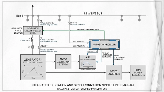
Industry guidance defines a strict sequence: the excitation system establishes terminal voltage first, then synchronizing devices issue real-time correction signals to both the governor and the excitation system. The circuit breaker is only allowed to close once all acceptance criteria are satisfied, ensuring stable operation after paralleling.
What excitation and synchronization solutions actually include
Excitation and Synchronization Solutions coordinate generator voltage, speed, and breaker control as a unified process. The AVR excitation system establishes terminal voltage, and IEEE guidance states that synchronization can only begin once sufficient voltage is available (typically 70–80% of rated value). Voltage regulation may then be handled by the AVR or auto synchronizer, while the synchronizing circuit sends correction signals to adjust excitation current.
On the speed side, the synchronizer issues raise/lower commands to the governor to match frequency and phase with the bus. SEL documentation describes continuous measurement of both sides with correction pulses sent to governor and exciter until all closing criteria are satisfied and the breaker is allowed to close.
After synchronization, control shifts from matching electrical parameters to stable real and reactive power operation. DEIF and Woodward distinguish between active-load sharing on the real power side and voltage-reference control for reactive power or power factor on the excitation side.
How AVR, load sharing, and synchronization work together
A generator cannot synchronize well if the excitation side is weak, unstable, or incorrectly scaled. IEEE guidance notes that generator terminal voltage is established before speed can be controlled for synchronization, and that a slightly higher generator voltage at close can be beneficial because it avoids the unit absorbing vars from the system immediately after breaker closure.
Once the voltage side is healthy, the synchronizer matches the incoming machine to the bus. Official controller documentation shows that synchronizing can be configured in different ways depending on the application. Woodward, for example, documents both phase-matching and slip-frequency synchronizing, with phase matching used where rapid synchronization is needed and slip-frequency synchronizing used in other operating cases.
After the breaker closes, the real test begins: stable sharing. DEIF’s load-sharing guidance says active load can be shared equally as a percentage of nominal power in island mode, while the related voltage-control option provides constant voltage, constant reactive power, constant power factor, and reactive-load-sharing functions for paralleled generators. Woodward documentation similarly describes VAR/PF control as adjusting generator voltage until the desired reactive power or power factor is reached.
Where these solutions are most useful
These solutions are most valuable on sites with multiple generators, islanded plants, emergency standby systems, utility-connected power plants, and brownfield facilities where the existing control logic is incomplete or inconsistent. DEIF’s controller application guidance explicitly covers single-unit operation, synchronizing projects, islanded operation, and parallel operation with the mains, which mirrors the most common use cases seen in utility, industrial, and critical-power projects.
They are also especially useful when a project involves protection interfaces, bus-tie logic, remote SCADA visibility, or generator retrofits where older manual procedures are being replaced with automated or semi-automated synchronization.
Common Problems These Systems Are Meant to Prevent
1) Poor voltage build-up or unstable excitation at no-load
If the generator fails to establish a healthy terminal voltage, the synchronizing logic cannot achieve a reliable close. IEEE guidance explicitly links successful synchronization to the presence of sufficient generator voltage.
2) Incorrect phase rotation, PT wiring, or CT polarity
Proper synchronization requires correct electrical alignment. Woodward documentation states that bus phase rotation must match generator rotation, and that CTs and PTs must be connected to the correct phase terminals with correct polarity. DEIF also highlights phase-sequence alarms and configurable protection for generator and mains rotation errors.
3) Poor load sharing after breaker closure
After synchronization, improper tuning of active and reactive power controllers can lead to instability. DEIF notes that both active-load sharing and reactive control require correct adjustment, while Woodward warns that incorrect cross-current compensation may destabilize VAR/PF control. In practice, this can result in circulating reactive power, poor power factor, or generator hunting during operation.
Commissioning Checklist for Excitation and Synchronization Solutions
1) Verify voltage transformers, current transformers, and phase rotation
Before any live synchronization test, confirm PT ratios, CT polarity, correct wiring to matching phases, and proper phase rotation between generator and bus. Woodward documentation requires matching rotation between generator and bus, with correct CT/PT phase alignment and polarity. DEIF also includes phase-sequence alarms for both generator and mains measurements.
2) Confirm voltage build-up and AVR response
Do not initiate synchronization with weak or unstable voltage. IEEE guidance states that terminal voltage must be established by the excitation system before synchronization begins, typically at a sufficient operating level. At this stage, verify manual and automatic voltage raise/lower response.
3) Validate synchronizer mode and breaker close criteria
Confirm the configured synchronizing method (phase matching, slip-frequency, or dead-bus logic). Ensure the breaker close command is enabled only when all acceptance criteria are met. SEL documentation states that autosynchronizers permit breaker closure only after synchronization conditions are satisfied.
4) Verify governor and excitation correction signals
Ensure the synchronizer correctly issues both speed correction signals to the governor and voltage correction signals to the excitation system. A functional test must validate both control paths independently before any live synchronization attempt.
5) Test load sharing and reactive power control
In island operation, verify active-load sharing between generators. DEIF confirms that active and reactive load sharing can be configured as a percentage of nominal power. In grid-parallel operation, confirm the selected control mode (constant VAR, constant power factor, or equivalent), as defined by the system design.
6) Verify stability after breaker closure
A successful close is not sufficient. Monitor system behavior under load changes, including voltage reference movement and MW/MVAr sharing stability. Vendor guidance highlights that improper AVR or sharing configuration may lead to instability in both active and reactive power control.
7) Verify alarms, trips, and protection integration
A specialized synchronizing scheme still needs protection discipline. Generator-side voltage and phase-sequence alarms, breaker fail behavior, synchronizing supervision, and associated types of protection relay in power system should be checked together so a commissioning test does not prove only the control path while leaving the protection path assumed. IEEE’s current practices for generator synchronizing systems explicitly include commissioning practices and methods to detect, alarm, or trip for out-of-phase synchronizing events.
Power Factor Control vs Reactive Load Sharing
These two concepts are often confused in project discussions, but control system documentation treats them as distinct functions. DEIF’s voltage control options include constant reactive power, constant power factor, and reactive load sharing as separate operating modes. Woodward VAR/PF control logic similarly shows that the controller can compare either kVAR or power factor against a reference and adjust the voltage regulator to achieve the required operating condition.
This distinction is important both technically and operationally. In islanded operation, paralleled generators typically prioritize balanced reactive load sharing, while grid-connected units are more focused on maintaining a defined power factor or reactive power import/export target. Selecting the wrong control objective may result in correct equipment behavior that still feels incorrect in system operation.
Get Expert Support for Excitation and Synchronization Solutions
At Riyadh Al Etqan Co., we provide end-to-end engineering support for excitation and synchronization solutions, covering system design, integration, testing, and commissioning. Our team ensures accurate voltage control, reliable synchronization, and stable load sharing across all operating modes, whether in islanded or grid-connected systems.
With a focus on practical site performance and compliance with industry standards, we deliver solutions that are fully tested, properly configured, and ready for long-term operation. Contact our team to discuss your project requirements or request technical support.
Conclusion
Excitation and synchronization solutions are not standalone components, but integrated control systems that ensure safe generator connection and stable operation under all conditions. From voltage build-up and synchronization logic to load sharing and protection coordination, each function plays a critical role in overall system performance.
A well-designed and properly commissioned system minimizes operational risks, prevents instability, and ensures reliable power generation in both islanded and grid-connected applications.
FAQ
What does an AVR do during generator synchronization?
The AVR establishes terminal voltage and then responds to voltage-correction commands during synchronization and reactive-power control afterward. IEEE guidance and vendor materials both describe the excitation system as the voltage-control side of the process.
What is the difference between load sharing and power factor control?
Load sharing balances generator contribution, while power-factor control regulates the reactive relationship between the generator and the system. Official controller documentation lists active-load sharing, reactive-load sharing, constant reactive power, and constant power factor as different functions.
Why is phase rotation such a big commissioning issue?
Because a synchronizer depends on correct voltage measurement and phase relationship. Woodward and DEIF both document phase-rotation requirements and alarm handling for incorrect sequence on generator or bus measurements.
Why set generator voltage slightly high before close?
IEEE guidance notes that a slightly higher generator voltage can prevent the machine from absorbing vars from the system immediately at breaker closure, which is especially important on weak systems.