
coordination time interval overcurrent relay plays a critical role in preventing unnecessary trips and ensuring correct fault isolation in industrial power systems. In industrial power systems, feeder protection studies, and substation applications, overcurrent relay coordination is used to balance speed, selectivity, and reliability. If relay timing is set too close, two devices may trip together. If it is set too far apart, fault clearing may become slower than the system can comfortably tolerate.
This article explains what relay coordination time interval means, how overcurrent relay settings are normally reviewed, what TMS means, common coordination problems, and the practical testing and maintenance steps that help keep the protection scheme dependable.
What is Coordination Time Interval Overcurrent Relay?
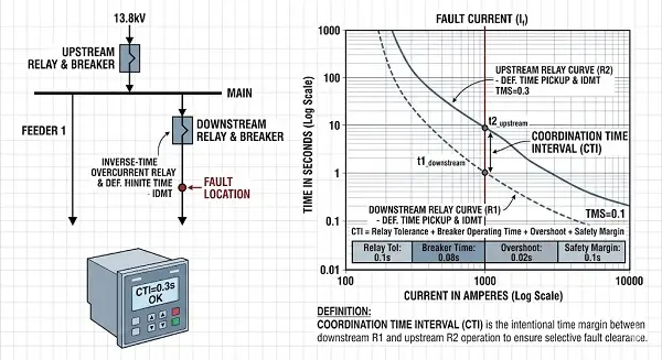
coordination time interval overcurrent relay is the intentional time separation between two relays that protect different parts of the system. The coordination time interval, often shortened to CTI in coordination studies, is the time margin intentionally maintained between the operation of a downstream overcurrent relay and the upstream relay that backs it up. Its purpose is to make sure the nearest protective device clears the fault first, while the upstream device remains available as backup if the downstream device or breaker does not clear correctly.
This interval usually has to account for more than relay operating time alone. It commonly considers:
- Relay operating time tolerance.
- Circuit breaker interrupting time.
- Overshoot or reset behavior in some relay designs.
- CT error, measurement uncertainty, and the safety margin required by the owner’s protection philosophy.
The exact value is not universal. It is selected according to the relay technology, the breaker performance, the system study method, and the standard or owner practice used on the project.
Read About: Types of Protection Relay in Power System (Full Guide)
What is the Time Interval in Relay Systems?
The time interval is the practical margin that allows selectivity between two protective devices. In protection studies, this interval represents the minimum time gap that ensures one protective device operates before the next upstream device begins its backup role. The chosen value depends on the type of relays whether electromechanical, static, or numerical as well as the operating speed of the associated breakers and the level of operating tolerance required by the system owner.
In practice, engineers usually review the time interval against:
- The downstream relay operating curve at the relevant fault current.
- The upstream relay operating curve at the same point on the network study.
- Breaker clearing time and relay tolerance margin.
- The applicable utility, consultant, or owner coordination criteria.
A coordination interval that looks acceptable on a curve should still be reviewed against breaker data and real operating conditions. This is why settings are normally confirmed through a protection study rather than by one fixed rule.
How to Calculate Overcurrent Relay Settings?
Relay settings should always be calculated from actual system data, not by copying values from another feeder. Overcurrent relay settings are determined by combining load data, fault levels, CT ratios, relay characteristic curves, and the desired coordination philosophy. The main goal is to ensure the relay operates above the maximum expected load or permissible overload, while still remaining sensitive enough to detect and clear faults effectively.
A practical settings workflow usually includes:
- Confirm the protected equipment, single-line diagram, and fault study assumptions.
- Select the CT ratio and review expected load current and minimum/maximum fault current.
- Choose the relay characteristic, such as definite time or IDMT where applicable.
- Set pickup current above load but within the sensitivity required for fault detection.
- Adjust time settings or TMS so that the relay coordinates properly with downstream and upstream devices.
The final settings should always be reviewed against the approved coordination study, site requirements, and the relay manufacturer’s guidance for the chosen characteristic.
Read About: Protection Relay Configuration: Engineering Guide
What is Coordination of Overcurrent Relays?
Coordination of overcurrent relays means arranging relay settings so that the closest protective device operates first while backup protection remains available. Coordination of overcurrent relays is the process of selecting pickup values and operating times so that multiple relays in a power system do not trip unnecessarily together. The target is selective fault isolation. In other words, the relay nearest the fault should clear first, while other relays higher in the system remain available if backup protection is needed.
Good coordination usually aims to achieve:
- Selectivity between feeder, incomer, and upstream source protection.
- Acceptable fault-clearing speed without unnecessary delay.
- Backup protection if the primary relay or breaker does not operate correctly.
- Protection settings that still reflect the actual fault levels and loading of the system.
Coordination is usually represented on time-current curves, but it should also be supported by settings files, breaker data, and documented engineering review.
How to Do Relay Coordination?
Relay coordination should follow a study-based method rather than trial-and-error setting changes. Relay coordination is normally carried out through a protection study in which system fault levels, load currents, CT data, relay characteristics, and breaker performance are reviewed together. The study is not only a calculation exercise; it also confirms that the protection philosophy remains practical for the actual network configuration.
A practical coordination sequence often includes:
- Build or verify the single-line diagram and network data used for the study.
- Review fault levels, source conditions, transformer data, and feeder arrangement.
- Select relay characteristics suited to the protected circuits.
- Plot downstream and upstream relay curves on the same study basis.
- Adjust pickup and timing so the required coordination margin is maintained.
- Check settings for both normal configuration and any expected alternate operating mode.
Coordination should be reviewed again whenever the network changes, major loads are added, breaker characteristics change, or relay replacements are introduced.
What is the TMS Setting of a Relay?
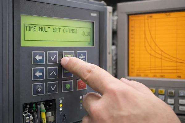
TMS controls the operating time of inverse-time relay curves and plays a key role in coordination studies. TMS stands for Time Multiplier Setting. In inverse-time overcurrent relays, it determines how fast or slow the relay operates by scaling the operating time of the selected curve, while the pickup setting remains unchanged. In simple terms, after selecting the curve type, the TMS adjusts the relay’s response time for fault currents above the pickup level.
In practical use, TMS is important because it helps engineers:
- Coordinate one inverse-time relay with another relay on the same protection path.
- Maintain a required time margin without changing the current pickup unnecessarily.
- Adjust the overall speed of response to fit the protected equipment and breaker arrangement.
The exact meaning and naming may vary slightly by relay manufacturer, but the coordination purpose remains the same: it helps position the relay on the time-current study.
Read About: How to Fix Power Supply Relay Failure?
Common Problems in Overcurrent Relay Coordination
Most coordination problems arise from outdated system data, incorrect assumptions, or unreviewed changes after installation. Overcurrent relay coordination issues often appear after network modifications, equipment upgrades, or settings changes that were not fully validated against the original protection study. In some cases, the relay operates correctly according to its settings, but those settings no longer reflect the actual system conditions.
Common problems include:
| Problem | Description |
|---|---|
| Pickup settings that are too low | Create nuisance operation during load or inrush conditions |
| Timing margins that are too small | Cause loss of selectivity between relays |
| Breaker operating times not included correctly | Affect the coordination margin |
| CT ratio or CT saturation issues | Distort measured current during faults |
| Settings changes without updating study records | Create mismatch with original coordination study |
Testing and Maintenance Tips for Overcurrent Relays
Testing and maintenance are essential because coordination is only as reliable as the actual performance of relays and breakers. Relay coordination does not end with the study. The relays and associated breakers must continue to operate in line with the assumptions used during the engineering process. For this reason, testing and maintenance remain critical throughout the entire equipment lifecycle.
A practical maintenance and testing routine may include:
- Verification of relay settings against the approved settings file.
- Functional or secondary injection testing according to the approved procedure.
- Review of trip circuit condition and breaker operating time where required.
- Inspection of event logs, self-supervision alarms, and communication records.
- Confirmation that any relay replacement, firmware update, or breaker change has been reflected in the coordination review.
The exact maintenance interval depends on the relay technology, asset criticality, owner practice, and service history.
Our Approach to Reliable Relay Coordination
At Riyadh Al-Etqan Company (R-Aletqan), we deliver reliable relay coordination through precise engineering review, accurate settings control, and disciplined follow-up after every change. Our approach is specifically designed to meet Saudi Arabia’s industrial grid requirements, ensuring protection systems perform as intended and remain fully aligned with both your network conditions and local utility standards.
Whether you are facing coordination issues, need a settings verification, or require support in testing and documentation, our team provides practical, engineering-based solutions to improve protection performance and system reliability.
If you need reliable relay coordination support or want to verify your protection system performance, contact us to get a professional review and practical engineering guidance.
Conclusion
coordination time interval overcurrent relay should be treated as an engineering decision supported by study data, settings control, and verified equipment performance. When pickup values, TMS, breaker times, and coordination margins are reviewed together, protection becomes more selective and the risk of unnecessary tripping is reduced.
To review our capability presentation and discuss your overcurrent relay coordination needs, view the company presentation and contact Riyadh Al-Itqan Company to book a discussion and request a quotation. View the presentation
FAQ
what is type1 and type2 coordination ?
Type 1 and Type 2 coordination are terms commonly used in motor starter and control equipment coordination under IEC-based product practice, especially for contactors and protective devices under short-circuit conditions. They are not the same as overcurrent relay selectivity studies, although both relate to how protective devices behave together. The exact definition should be taken from the applicable product standard and equipment manufacturer documentation.
what is CTI in relay?
CTI usually refers to the Coordination Time Interval. It is the intentional time margin maintained between a downstream protective device and the upstream backup device so the nearer device has time to clear the fault first.
Are these procedures applicable to all types of overcurrent relays?
The overall coordination principles apply broadly, but the detailed procedure depends on relay technology, relay characteristic, breaker data, system arrangement, and the owner’s standards. Electromechanical, static, and numerical relays may require different assumptions for timing accuracy, tolerances, and maintenance methods.