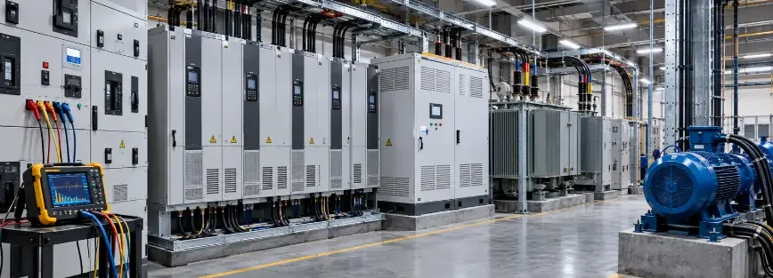
Harmonic mitigation techniques in power quality become critical when electrical systems start showing signs of stress that cannot be explained by normal loading alone. Transformers running hotter than expected, capacitor banks failing prematurely, and drives tripping unexpectedly can indicate excessive harmonic distortion somewhere in the system.
In Saudi industrial plants, where LV and MV systems support automation and motor drives, these problems are often linked to non-linear loads such as variable frequency drives and converters. This guide covers the main harmonic mitigation methods, where each one fits, and how to choose between them.
What Are Harmonic Mitigation Techniques in Power Quality?
Harmonic distortion occurs when electrical waveforms deviate from their ideal sinusoidal shape. Unlike linear loads that draw current in proportion to the applied voltage, non-linear equipment draws current in pulses, producing additional frequency components known as harmonics.
Harmonic mitigation techniques in power quality, also known as harmonic mitigation methods, are used to reduce the effects of harmonic currents and distortion on electrical systems. They include line reactors, multi-pulse transformers, isolation transformers, and active front-end drives, as well as passive and active harmonic filters.
For more detail on filter-based solutions, see our guide to [harmonic filters in power systems]. Engineers select the appropriate approach based on harmonic analysis, the system configuration, the characteristics of the loads, and the sensitivity of connected equipment.
Signs Your System Needs Harmonic Mitigation
Harmonic problems rarely announce themselves. They often appear as symptoms that may initially seem unrelated:
- Unexpected overheating: Transformers, cables, and motors may run hotter than expected even when RMS current does not appear unusually high, because harmonic currents can increase additional heating losses.
- Overloaded neutral conductors: In four-wire systems with significant single-phase non-linear loads, triplen harmonics can accumulate in the neutral conductor rather than cancel.
- Nuisance tripping and blown fuses: Unexpected breaker or drive trips, as well as repeated capacitor bank fuse failures, can indicate harmonic-related stress or resonance.
- Motor noise and vibration: Harmonic distortion can contribute to additional motor losses, torque pulsations, audible noise, and vibration.
- Erratic behavior of sensitive equipment: PLC resets, instrumentation errors, or other abnormal equipment behavior can occur when power quality deteriorates, particularly during changes in large drive loads.
These symptoms can point to a harmonic problem, but they do not confirm its cause. Confirmation requires measurement through a power quality assessment, including voltage and current harmonic measurements at appropriate points in the system. The results can then be evaluated against applicable IEEE 519 requirements and other relevant power quality criteria to determine whether further investigation or mitigation is warranted. See our [power quality analysis services] to learn how these measurements are performed.
Line Reactors and Chokes: The First Line of Defense
Line reactors are three-phase inductors installed on the input side of a drive or converter. By adding impedance to the supply path, they reduce the sharp current pulses produced by six-pulse rectifiers, helping lower input current distortion. DC-link chokes used inside many modern drives work on a similar principle.
As one of the simpler harmonic mitigation techniques in power quality, line reactors offer relatively low cost, simple installation, and no tuning requirements. They also help protect the drive’s rectifier from voltage spikes and supply disturbances.
Their limitations matter as well:
- They reduce but do not eliminate harmonics: On their own, reactors may not provide enough reduction to meet applicable IEEE 519 requirements where drives make up a large share of the load.
- Additional benefit may be limited when a drive already has a DC-link choke: The existing drive configuration should be checked before adding another reactor.
- Line reactors are commonly available in standard impedance ratings: Higher impedance can provide greater harmonic reduction, but it also results in a larger voltage drop that should be considered during selection.
- Output reactors are different: They help protect the motor from fast voltage changes but do not provide supply-side harmonic mitigation.
For individual drives, this makes line reactors a sensible first step when basic harmonic reduction is required. When they are not sufficient, engineers may consider multi-pulse systems, active front-end drives, or harmonic filters based on measured system conditions.
Isolation Transformers for Harmonic Isolation
An isolation transformer separates harmonic-producing loads from other parts of the electrical network, helping limit the propagation of harmonic distortion to sensitive equipment. A delta-wye configuration traps circulating triplen harmonic currents, such as the 3rd and 9th, in the delta winding, reducing their flow into the upstream system. The galvanic isolation also helps block common-mode noise between the supply and sensitive loads.
Isolation transformers can be useful where drives and sensitive control or instrumentation loads share a supply, or where triplen harmonics from single-phase non-linear loads contribute to neutral conductor loading.
Their limitations include limited effectiveness against the 5th and 7th harmonics produced by typical six-pulse drives, as well as added cost, space, and voltage drop. Transformers supplying significant harmonic loads may also require appropriate K-rating or derating to manage additional heating.
Multi-Pulse Transformers and Converters (12-Pulse, 18-Pulse)
Multi-pulse systems use phase-shifting transformers and multiple rectifier bridges to reduce selected harmonics from six-pulse drives. The bridges are supplied with phase-shifted voltages, causing their harmonic currents to partially offset each other. They can be configured as a separate transformer with standard drives or as a drive with a multi-bridge input stage.
- 12-pulse (30° shift): Reduces the 5th and 7th harmonics, with the 11th and 13th becoming dominant.
- 18-pulse (20° shift): Further reduces the 11th and 13th harmonics, with the 17th and 19th becoming dominant.
They suit large, continuously operating drives where lower harmonic distortion justifies the higher cost and installation space. Their effectiveness depends on balanced operation, and they do not eliminate all harmonics. They are also best specified during the design stage, as retrofitting an existing six-pulse drive can require replacing the drive or its input stage.
Active Front-End (AFE) Drives as a Harmonic Solution
An active front-end (AFE) drive replaces the conventional diode rectifier with a controlled IGBT converter that shapes the input current into a near-sinusoidal waveform. An LCL filter helps reduce switching ripple, allowing the AFE to address harmonic distortion at the drive input without typically requiring a separate harmonic filter or phase-shifting transformer.
AFE drives can also provide regenerative braking, returning energy to the supply during braking. This makes them useful for applications such as conveyors, cranes, hoists, and test benches. They can also operate at near-unity power factor and provide reactive power control in some designs.
They suit large, critical, or regenerative drives, particularly where low harmonic distortion is required and multi-pulse solutions are impractical. Their main limitations are higher cost and complexity, additional losses and space requirements associated with the switching stage and LCL filter, high-frequency switching emissions that must be properly managed, and the need to evaluate performance under weak or unbalanced supply conditions.
How to Choose the Right Harmonic Mitigation Technique
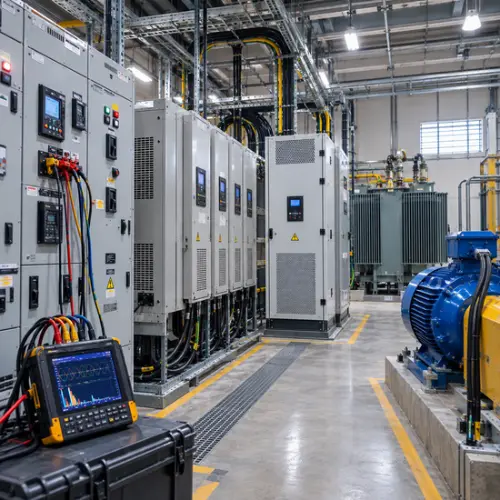
Selecting the right harmonic mitigation techniques requires a structured engineering process based on measured system conditions rather than equipment selection alone.
- Assess and identify the sources: Measure voltage and current harmonics and analyze the harmonic spectrum under relevant equipment operating conditions through a power quality assessment. Determine which loads generate the harmonics, when and where distortion increases, and which equipment is most affected.
- Review the electrical system: Consider the transformer arrangement, LV and MV configuration, distribution system, supply strength, existing protection and control equipment, and the sensitivity of critical control and production equipment.
- Compare mitigation options: Evaluate solutions based on harmonic levels, load characteristics, operating conditions, installation requirements, maintenance, cost, and future expansion plans.
- Verify the result: After implementation, repeat the relevant measurements at appropriate points, including the point of common coupling where applicable, and evaluate the results against applicable IEEE 519 requirements and other relevant power quality criteria.
The appropriate solution depends on the measured conditions. For example, line reactors may suit individual drives with moderate distortion, while multi-pulse or AFE solutions may be considered for large continuous drives. Where significant distortion remains, passive or active harmonic filters may be evaluated based on the system configuration and harmonic profile.
Common Mistakes When Combining Multiple Mitigation Techniques
Combining harmonic mitigation techniques can be effective, but applying multiple measures without evaluating their interaction can create new problems.
- Overlapping measures: Adding a line reactor to a drive that already has a DC-link choke may add cost and voltage drop with limited additional benefit.
- Creating resonance: Adding capacitors or passive filters to a network with existing capacitor banks can create resonance at certain frequencies and amplify harmonic distortion. The network should be evaluated before adding capacitive elements.
- Combining passive filters with AFE drives: Capacitive filtering can interact with the AFE control system and LCL filter, so the combination should be properly engineered rather than assumed to be compatible.
- Ignoring multi-pulse system balance: Harmonic cancellation in multi-pulse systems depends on balanced operation. Adding another mitigation technique does not correct an underlying bridge or load-sharing imbalance.
- Installing multiple measures without verification: When several solutions are applied together, their individual contribution can be difficult to assess. Where practical, verify the effect of each stage through measurement before adding further mitigation.
RETQAN: One Partner for Every Harmonic Mitigation Solution
RETQAN supports industrial facilities in identifying and addressing harmonic problems across LV and MV electrical systems. Our engineering approach covers harmonic mitigation techniques in power quality, from line reactors, multi-pulse systems, isolation transformers, and AFE drives to passive and active harmonic filters. We begin with power quality assessment and system analysis to understand harmonic sources, operating conditions, and network configuration before recommending a suitable solution.
Our support extends from assessment and engineering through supply, installation, commissioning, and verification.
FAQ
Which harmonic mitigation technique is the most cost-effective?
It depends on the system. For individual drives with moderate distortion, line reactors or DC chokes can be economical options, while larger drives may justify multi-pulse or AFE solutions. Measurement should guide the choice.
Can multiple harmonic mitigation techniques be combined in one system?
Yes. Different techniques can be combined when properly engineered. For example, line reactors can be used on individual drives alongside a harmonic filter at the main bus. Their interaction should be evaluated to avoid issues such as resonance.
Do multi-pulse transformers eliminate harmonics completely?
No. They reduce selected low-order harmonics. Under balanced conditions, 12-pulse systems reduce the 5th and 7th, while 18-pulse systems also reduce the 11th and 13th. Higher-order harmonics remain.