
Power supply relay failure is one of the most common causes of control circuit problems in industrial systems. A single relay fault can turn a minor issue into a major electrical interruption, leading to unexpected trips, equipment damage, or system instability. Understanding the causes, symptoms, and relay troubleshooting steps is essential to quickly identify the problem and prevent costly downtime. This guide explains practical diagnostic methods, testing procedures, and preventive measures to ensure reliable relay performance in industrial environments.
What is Power Supply Relay Failure?
Power supply relay failure refers to a condition in which a relay no longer performs its intended switching or control function correctly. This failure may be complete, such as a relay that no longer energizes or changes state, or partial, such as delayed operation, contact instability, overheating, or inconsistent switching under load.
In practical plant conditions, this failure may involve:
- A coil that does not energize when the control signal is present.
- Contacts that remain stuck open or stuck closed.
- Contacts that operate but with poor continuity, chattering, or excessive voltage drop.
- Mechanical wear that affects the relay armature or return action.
- Heat or contamination damage that changes performance over time.
The exact failure mode should always be confirmed by inspection, measurement, and approved testing rather than by assumption alone.
What Is the Purpose of a Power Relay in Electrical Systems?
Understanding the purpose of a power relay helps make troubleshooting more accurate, as any failure should be evaluated against the intended function. A power relay is used to control one circuit by means of another circuit. In electrical and industrial control applications, this typically means that a lower-power control signal is used to open or close contacts that influence a higher-current load, a logic path, or a protective sequence.
Depending on the application, a power relay may be used to:
- Switch motors, contactors, solenoids, lamps, and auxiliary control circuits.
- Provide isolation between control logic and the load side.
- Support automation sequences in control panels and machine logic.
- Transfer status or trip commands between protective and control circuits.
- Provide interlocking or enable/disable functions in electrical systems.
The purpose of the relay should always be reviewed against the single-line diagram, control schematic, and the actual operating sequence before any repair decision is made.
Main Causes of Power Relay Failure
Power supply relay failure are often caused by electrical stress, mechanical wear, or unsuitable operating conditions. Relays can fail for several reasons, and accurate diagnosis depends on the relay type, duty cycle, connected load, and environmental conditions.
In many industrial cases, failure is not caused by a single factor but results from repeated stress combined with weak maintenance or incorrect relay selection.
Common causes include:
- Voltage spikes, transient overvoltage, or switching surges that place stress on the coil and contacts.
- Contact wear due to frequent operation under inductive loads or high inrush currents.
- Overheating caused by continuous operation beyond the relay’s rated duty cycle or insufficient panel ventilation.
- Dust, corrosion, moisture, or contamination affecting internal components or terminals.
- Loose terminals or poor connections that increase resistance, heat, and reduce switching reliability.
- Mechanical fatigue in electromechanical relays after long periods of use.
- Incorrect relay selection in terms of voltage, current rating, coil type, or load category.
Lightning-induced surges and electrical switching transients may also contribute to failure. These conditions should be evaluated using system records and the condition of protective devices rather than relying solely on visual inspection.
Common Symptoms of Relay Failure
Relay failure symptoms may appear as clear electrical faults or as intermittent control problems that are harder to trace. A structured review should compare the symptom on the live system with the relay’s design function and control sequence.
Common symptoms include:
- The relay coil receives a command but the contacts do not change state.
- Chattering, buzzing, or unstable pickup and dropout behavior.
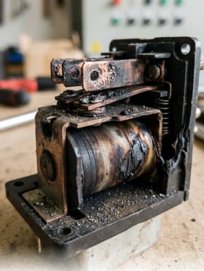
- Visible overheating, discoloration, or burn marks near relay terminals or contacts.
- A load that remains energized when it should release, or fails to energize when commanded.
- Intermittent faults that appear under vibration, high temperature, or load switching conditions.
- Repeated nuisance trips or loss of control continuity in connected equipment.
Some symptoms can resemble wiring faults, control logic errors, or power quality problems. That is why relay failure should be confirmed through a systematic diagnosis rather than through symptom matching alone.
Read about: Types of Protection Relay in Power System
how to solve relay problem?
Power supply relay troubleshooting should always follow evidence, not guesswork, because an incorrect relay replacement can hide the real cause. The process starts with identifying whether the failure lies in the relay itself, the coil supply, the contact path, the connected load, or the wider control logic.
In practical maintenance work, the first safe corrections usually include the following steps:
Step 1: Confirm that the correct control voltage is reaching the relay coil under operating conditions.
Step 2: Check for loose, damaged, or overheated terminals and terminations.
Step 3: Inspect the relay socket, plug-in base, and terminal tightness where applicable.
Step 4: Verify the load current and confirm that the relay rating matches the actual duty.
Step 5: Review whether the failure followed a surge event, overload, or recent wiring change.
Step 6: If relay replacement is required, ensure the replacement matches the approved specification, rating, coil type, contact arrangement, and duty category.
Following these structured steps ensures that the root cause is addressed, prevents unnecessary replacements, and protects connected equipment from further damage.
How to Diagnose and Solve Relay Problems
Diagnosis should move from the power supply and control inputs toward the contacts and load circuit. A proper relay diagnosis is usually done in stages. This helps the team confirm whether the problem is electrical, mechanical, or application-related.
A structured diagnostic sequence often includes:
- Step 1: confirm the relay identity, rating, and intended function in the circuit.
- Step 2: measure coil voltage under normal and fault conditions.
- Step 3: verify pickup and dropout behavior, where safe and approved to do so.
- Step 4: inspect contact continuity and contact resistance condition where applicable.
- Step 5: review the connected load for overcurrent, inrush, or abnormal switching stress.
- Step 6: compare findings with recent maintenance history, alarm logs, and prior replacements.
This sequence helps avoid replacing a relay when the real issue lies in the upstream control signal, the downstream load, or the environmental conditions around the panel.
Testing Methods for Power Relays
Power relay testing methods are essential to verify relay condition with measurements rather than relying solely on appearance. Proper testing ensures the relay performs reliably under operating conditions and helps prevent unexpected failures.
The process typically follows these structured steps:
Step 1: Measure coil resistance to identify open-circuit, shorted, or abnormal winding conditions.
Step 2: Perform insulation and continuity checks where applicable and approved.
Step 3: Conduct functional pickup and dropout testing using the correct test voltage.
Step 4: Verify contact continuity in each operating state to ensure reliable switching.
Step 5: Carry out a visual inspection for discoloration, mechanical damage, contamination, or loose parts.
Step 6: Perform a thermal review of the relay and terminations where overheating is suspected.
Step 7: Retain testing records for critical installations, allowing comparison of recurring failures over time.
Following these steps ensures accurate diagnosis, protects connected equipment, and maintains reliable relay performance across industrial systems.
Preventive Measures and Maintenance of Relays
Preventive maintenance for power relays is the most effective way to reduce unexpected relay-related interruptions. A planned approach allows early detection of heat stress, terminal issues, contamination, and wear from repeated duty before the relay fails.
Practical preventive steps include:
Step 1: Conduct routine inspection of relay condition, terminals, sockets, and surrounding panel cleanliness.
Step 2: Verify relay ratings against any changes in load or operating sequence.
Step 3: Perform thermal checks if repeated heating or discoloration is observed.
Step 4: Plan replacement for relays with high duty cycles or known wear history.
Step 5: Review surge protection, suppression devices, and control power quality where coil stress is suspected.
Step 6: Keep approved spare relays with correct ratings and part numbers for critical systems.
Step 7: Follow preventive intervals based on asset criticality, switching duty, manufacturer guidance, and site maintenance policy.
Following these preventive measures ensures reliable relay performance, reduces downtime, and protects connected equipment from unexpected failures.
Types of Power Supply Relays and Their Vulnerabilities
Power supply relays are not all the same. Different technologies and applications bring different strengths and vulnerabilities.
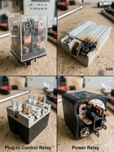
Common relay categories and their typical vulnerabilities include:
- Electromechanical relays: vulnerable to mechanical wear, contact erosion, contamination, and vibration effects.
- Solid-state relays: vulnerable to heat stress, component degradation, and sensitivity to surge conditions if protection is poor.
- Plug-in control relays: vulnerable to loose socket contact, oxidation, and poor retention in high-vibration conditions.
- Heavy-duty power relays or contact relays: vulnerable to contact damage under high inrush or inductive switching duty.
The right maintenance and replacement strategy depends on which relay technology is installed and how that relay is being used in the system.
Safety Precautions While Handling Relays
precautions for handling power relays are essential to protect personnel and equipment during maintenance or testing. Even a small control relay can affect motors, breakers, interlocks, or protective sequences.
Key safety steps include:
1: Follow approved isolation, permit, and lockout/tagout procedures before any work.
2: Confirm the status of connected loads and interlocks before removing or bridging any relay.
3: Use correct test instruments and approved voltage ranges during relay checks.
4: Avoid touching energized terminals, exposed conductors, or adjacent live parts.
5: Document any temporary bypass, substitution, or control sequence change during testing.
6: Exercise extra caution when relay work is performed in panels containing contactors, breakers, variable speed drives, or other energy-bearing components.
Adhering to these safety precautions ensures maintenance is conducted without risk, protecting both personnel and critical electrical systems.
Stop Unexpected Relay Failures – Protect Your Plant Today!
Power relay failures can halt your production, cause false alarms, and stress critical equipment. Riyadh Al-Etqan Company (R-Aletqan) ensures your relays work reliably with expert diagnosis, testing, and maintenance.
How we help:
Action 1: Spot relay faults before they interrupt your system.
Action 2: Plan maintenance and testing for critical circuits.
Action 3: Keep organized records for future replacements.
Action 4: Ensure smooth integration with switchgear, motors, and control logic.
Conclusion
power supply relay failure should be treated as a technical warning sign rather than as a simple part replacement issue. When teams understand relay purpose, common causes of failure, diagnostic methods, testing requirements, and preventive measures, they are better prepared to reduce unexpected interruptions and protect connected electrical equipment.
To review our capability presentation and discuss your relay failure concerns, view the company presentation and contact Riyadh Al-Itqan Company to book a discussion and request a quotation. View the presentation
FAQ
How often should relays be tested?
The testing interval should follow the site’s maintenance policy, the relay duty cycle, the criticality of the circuit, and the manufacturer’s recommendations. Critical or frequently operated relays may justify more frequent inspection and functional checks than relays used only occasionally.
Can a relay fail due to voltage spikes or lightning?
Yes, relay failure can be influenced by voltage spikes, switching surges, or lightning-related transient conditions, especially where surge protection or suppression is weak. The exact contribution should be reviewed using maintenance history, event records, and protective device condition.
What are the signs of mechanical wear in an electromechanical relay?
Common signs include sluggish movement, inconsistent pickup or dropout, contact chatter, visible wear or discoloration at the contact area, and performance changes after long service under repeated operation.