
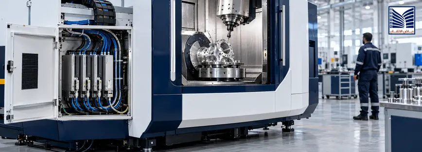
Industrial communication protocol selection for PLC and variable frequency drive (VFD) integration should be based on device compatibility, required data exchange, network architecture, diagnostics, application performance, and long-term support. Modbus TCP, PROFINET, and EtherNet/IP use different communication models and engineering approaches, so choosing one based only on brand preference or Ethernet connectivity can create integration and maintenance problems. Engineers should first confirm which protocols the actual controller and drive support, define the required command and feedback data, and review the network and commissioning requirements before approving a design or purchasing equipment.
Quick Answer: Which Industrial Communication Protocol Should You Choose?
There is no universally best industrial communication protocol for every PLC and drive application. Modbus TCP may suit register-based data exchange between compatible devices, while PROFINET and EtherNet/IP provide broader industrial automation communication capabilities that depend on the supported implementation. The right choice depends on the installed controller and drive ecosystem, required process-data exchange, diagnostics, network design, engineering tools, and available maintenance expertise. Confirm compatibility using the actual device manuals and supported communication options before making a procurement decision.
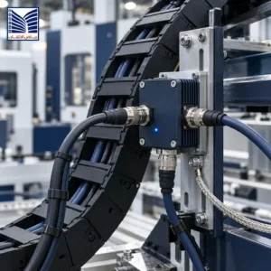
Why Industrial Communication Protocol Selection Matters
Industrial communication connects controllers, drives, remote I/O, instruments, operator interfaces, and other automation devices. The selected protocol influences how these devices exchange information, how engineers configure them, and how maintenance teams diagnose communication faults.
A protocol decision can affect several areas of an industrial project:
- PLC-to-drive communication: determines how supported commands, references, status information, and diagnostics are exchanged.
- Device interoperability: establishes whether the controller and connected device can communicate using compatible protocol implementations and data definitions.
- Control architecture: influences how process data is organized and exchanged between devices.
- Diagnostics and fault isolation: affects which communication errors and device-level diagnostic information can be accessed.
- Commissioning effort: determines which configuration tools, data maps, device descriptions, and tests may be required.
- Network maintenance: influences how technicians investigate communication interruptions and device configuration problems.
- Future expansion: affects how additional devices and interfaces can be incorporated into the existing architecture.
- Lifecycle support: requires consideration of product availability, software compatibility, documentation, spare parts, and engineering skills.
An important distinction is that communication compatibility does not automatically mean functional compatibility. Two devices may use the same protocol but still have different register maps, supported commands, diagnostic functions, configuration requirements, or control-mode limitations. Successful Ethernet connectivity alone does not prove that a complete PLC-to-VFD application will operate as intended.
Modbus TCP vs PROFINET vs EtherNet/IP: Key Differences
Modbus TCP
Modbus TCP is an industrial application-layer messaging protocol that supports client/server communication over TCP/IP networks. A client initiates a request, and the server processes it and returns a response. The protocol defines function codes and data-access behavior, while the device implementation determines which functions and data points are supported.
For PLC and VFD integration, Modbus TCP may be suitable when the controller and drive both support the protocol and the required information can be exchanged through their documented data structures.
Important engineering considerations include:
- Register and data mapping: identify the documented registers for commands, references, feedback, status, and diagnostics.
- Supported function codes: verify which read and write operations are supported by the specific device.
- Addressing: confirm the device addressing and register-offset conventions used by the controller and drive documentation.
- Data representation: check data types, word order, scaling, signed values, and engineering units where applicable.
- Update requirements: establish whether the request/response behavior meets the application’s required data-update characteristics.
- Timeout handling: verify how communication failures are detected and what action the application is designed to take.
- Diagnostics: determine which communication and device fault information is available.
- Implementation limitations: confirm the supported functions, connection capacity, and operating restrictions of the actual equipment.
Modbus TCP can be useful for straightforward data exchange, including monitoring and control functions supported by the connected devices. However, its availability does not automatically provide every real-time control, device-diagnostic, or integrated engineering feature that another automation implementation may offer. The actual suitability depends on the required behavior and the capabilities documented for both ends of the connection.
PROFINET
PROFINET is an industrial Ethernet communication technology used to connect controllers and devices in automation systems. Depending on the implementation, it supports cyclic process-data exchange, acyclic communication for parameters and diagnostics, and different real-time communication capabilities.
In a compatible PLC-to-VFD application, engineers may use PROFINET to exchange control data, speed references, drive status, feedback, and supported diagnostic information. The precise functions depend on the controller, drive, communication interface, device configuration, and supported application profile.
Key selection considerations include:
- Controller and device roles: confirm that the intended controller and drive support the required PROFINET roles and functions.
- Device configuration: review the applicable engineering tools and device-description files, such as GSDML where required.
- Cyclic process data: establish the required input and output data and the supported update behavior.
- Acyclic communication: check access to supported parameters, identification information, and diagnostics.
- Device identification: verify naming, addressing, and replacement requirements defined by the implementation.
- Network topology: confirm that the selected switches, ports, cabling, and topology are suitable for the system design.
- Real-time capabilities: identify which communication class and performance features the actual devices support.
- Maintenance tools: ensure that the engineering team can access the relevant configuration and diagnostic information.
Not all PROFINET implementations have identical capabilities. Engineers should avoid assuming that a device supports a particular real-time class, redundancy feature, or diagnostic function merely because it is described as PROFINET-compatible.
EtherNet/IP
EtherNet/IP is an industrial communication network that uses the Common Industrial Protocol (CIP) over Ethernet and IP networks. It supports explicit messaging for request/response operations and implicit messaging for application-specific I/O data exchange.
In EtherNet/IP systems, scanner and adapter roles are common in I/O communication, although the actual roles and supported features depend on the device. A PLC and VFD must support compatible communication functions and the required application data for the intended integration.
Important selection considerations include:
- Scanner and adapter roles: verify the communication roles supported by the controller and drive.
- Implicit messaging: confirm whether the required cyclic I/O data exchange is supported and properly configured.
- Explicit messaging: verify access to supported parameters, configuration services, and diagnostic information.
- I/O data mapping: confirm the relevant assemblies, data sizes, formats, and control/status definitions.
- Device configuration: review required electronic descriptions, configuration tools, and device-specific settings.
- Diagnostics: identify which communication, connection, and device-status information is available.
- Network design: review addressing, switches, traffic behavior, and any supported redundancy requirements.
- Device capabilities: confirm that the required functions are supported by the specific controller, drive, and communication interface.
EtherNet/IP should not be selected solely because a plant already uses Ethernet. The engineering team must confirm the controller’s supported communication options, the drive’s implementation, the required data exchange, and the project’s diagnostic and performance requirements.
Comparison Table: Modbus TCP vs PROFINET vs EtherNet/IP
The following table provides a general engineering comparison. It is not a substitute for checking the technical documentation of the specific devices under consideration.
| Engineering Factor | Modbus TCP | PROFINET | EtherNet/IP |
|---|---|---|---|
| Communication approach | Client/server request and response | Industrial automation communication with cyclic and acyclic services | CIP-based communication with explicit and implicit messaging |
| Typical integration considerations | Function codes, register maps, addressing, and data formats | Device configuration, process-data mapping, engineering tools, and supported communication classes | Scanner/adapter roles, I/O assemblies, messaging, and device configuration |
| Cyclic process data | Repeated requests can exchange data; timing depends on implementation and network conditions | Supported cyclic process-data exchange with implementation-dependent capabilities | Implicit I/O connections support regular data exchange where implemented |
| Diagnostics | Protocol exceptions and device-specific diagnostic data where supported | Device, module, channel, and network diagnostics where supported | Communication, connection, and device diagnostics where supported |
| Device configuration | Register maps and communication settings according to device documentation | Controller engineering and device-description/configuration requirements | Controller engineering, device descriptions, and supported CIP configuration |
| PLC-to-VFD integration | Suitable when both devices support the required register-based functions | Suitable when compatible PROFINET interfaces and required drive functions are available | Suitable when compatible EtherNet/IP interfaces and required drive functions are available |
| Engineering tool requirements | PLC configuration tools and relevant Modbus documentation or diagnostics | Compatible controller engineering tools and applicable device descriptions | Compatible controller engineering tools and applicable device configuration files |
| Network design considerations | IP addressing, TCP/IP connectivity, traffic, and device limits | Supported topology, device configuration, traffic, and applicable real-time requirements | Supported topology, IP configuration, I/O connections, and network traffic |
| Maintenance and troubleshooting | Register checks, request/response diagnostics, and timeout investigation | Device diagnostics, configuration review, and supported topology information | Connection status, I/O diagnostics, explicit-message tools, and device information |
| Best-fit considerations | Compatible applications requiring documented data exchange through supported functions | Systems whose installed automation ecosystem and requirements support PROFINET | Systems whose installed automation ecosystem and requirements support EtherNet/IP |
None of these protocols should be declared universally superior based on this comparison. Actual performance, supported data rates, device capacity, redundancy, and diagnostic depth depend on the implementation, hardware, software, configuration, and network design. Any quantitative requirement should be verified against the relevant technical documentation and application study.
What Should Engineers Check Before Selecting a Protocol?
1. Existing PLC and Automation Infrastructure
Begin by documenting the installed automation system. A protocol that fits the existing controller and engineering environment may reduce integration complexity, but only if the required device functions are also supported.
- Identify the installed PLC manufacturer, model, and firmware.
- Confirm available Ethernet ports and communication interfaces.
- Review the current network architecture and connected devices.
- Verify the protocol options supported by the controller.
- Check engineering software and configuration requirements.
- Confirm compatibility with existing devices and planned expansion.
When evaluating programmable logic controllers and automation solutions, engineers should consider the full control architecture rather than choosing a protocol in isolation.
2. VFD Communication Requirements
For PLC-to-VFD integration, define exactly which information must be exchanged and what the application expects the drive to do with it.
- Supported drive communication interfaces and optional modules.
- Required control and status words.
- Speed reference and actual-speed feedback.
- Parameter access and configuration requirements.
- Fault, warning, and operating-state reporting.
- Communication-loss detection and response.
- Local versus remote control selection.
- Required data-update behavior.
Control words, registers, parameters, scaling, and supported commands are device-specific. Verify them using the applicable drive manual and communication-interface documentation. Do not assume that two VFD models using the same protocol share identical data maps or control behavior.
Review the available industrial variable frequency drives options against the motor application, control requirements, installed PLC, and intended network.
3. Network Topology and Infrastructure
The network must support the intended devices and application requirements. Topology selection should follow the protocol implementation, equipment documentation, environmental conditions, and project architecture.
Review these factors:
- Supported star, line, ring, or other network arrangements.
- Industrial switches and other network components.
- IP addressing and network segmentation.
- Industrial cable selection and installation requirements.
- Network traffic and loading considerations.
- Redundancy requirements where supported.
- Environmental conditions, including temperature, dust, and electrical interference.
Do not assume that all switches, topologies, or redundancy methods are suitable for every protocol implementation. Confirm the requirements in the applicable network and device documentation.
4. Diagnostics and Maintenance
A communication architecture should be maintainable after commissioning. The ability to identify faults, access device information, and restore the correct configuration can be as important as the initial connection.
Review the following:
- Availability of communication and device diagnostics.
- Device-status and communication-error reporting.
- Methods for isolating network and configuration faults.
- Availability of qualified maintenance personnel.
- Spare communication modules and replacement planning.
- Configuration backups and device documentation.
- Procedures for replacing a device and restoring its configuration.
Diagnostic capability should be evaluated against the actual maintenance tasks the plant needs to perform. A protocol name alone does not establish how much diagnostic information a particular device exposes.
5. Lifecycle and Procurement Requirements
Procurement teams should confirm that the selected architecture can be supported throughout the expected service life of the equipment.
- Product availability and lifecycle status.
- Supported firmware and software versions.
- Access to engineering tools and licenses where applicable.
- Availability of OEM manuals and configuration documentation.
- Staff training requirements.
- Future device and network expansion requirements.
- Integration, commissioning, testing, and handover responsibilities.
Include these requirements in the technical specification or request for quotation (RFQ). Defining them before procurement reduces the risk of discovering missing interfaces, unsupported functions, or unclear commissioning responsibilities after equipment delivery.
How PLC-to-VFD Communication Works in Practice
In a typical PLC-to-VFD application, the controller exchanges supported command and reference data with the drive. The drive processes the received information according to its configuration, control mode, permissives, and applicable safety conditions, then returns status and feedback data supported by the selected interface.
The following illustrative sequence shows the conceptual data flow. It is not a commissioning procedure or a universal implementation.
PLC Controller
     |
     | 1. Prepare command and reference data
     v
Configured Industrial Network
     |
     | 2. Transfer supported communication data
     v
Variable Frequency Drive (VFD)
     |
     | 3. Validate data and apply configured control logic
     | 4. Execute requested action only when permitted
     v
Motor and Driven Equipment
     |
     | 5. Return supported status, feedback, and diagnostics
     v
PLC / HMI / SCADA Monitoring
     |
     | 6. Display operating state and identify relevant faults
     v
Operator and Maintenance Team
The sequence can be represented as a simplified message flow:
sequenceDiagram
    participant PLC as PLC Controller
    participant NET as Industrial Network
    participant VFD as Variable Frequency Drive
    participant HMI as HMI / SCADA

    PLC->>NET: Send configured command and reference data
    NET->>VFD: Transfer supported data
    VFD->>VFD: Validate command and operating conditions
    VFD-->>NET: Return supported status and feedback
    NET-->>PLC: Deliver returned data
    PLC-->>HMI: Publish status, feedback, and diagnostics
Actual projects may use different message types, update mechanisms, and control architectures. The required sequence must be established from the controller and drive documentation.
Communication availability alone does not prove that the drive is ready to operate, that the motor can safely start, or that the complete process-control system meets its safety requirements. Control mode, permissives, interlocks, fault handling, and safety functions must be considered separately according to the approved design.
Common Protocol Selection and Integration Mistakes
Several avoidable mistakes can increase engineering effort or create operational problems during commissioning and maintenance.
- Choosing a protocol without checking device support: the controller or drive may not support the required interface or function. Verify the exact model and communication option before procurement.
- Assuming Ethernet connectivity means application compatibility: devices may connect physically while using incompatible protocols or data definitions. Confirm application-level support.
- Ignoring the installed PLC and drive ecosystem: an isolated equipment choice may introduce additional engineering tools, configuration requirements, and maintenance skills. Assess the whole system.
- Failing to confirm the data map: incorrect registers, assemblies, scaling, or control/status definitions can produce misleading values or unintended behavior. Use the applicable OEM documentation.
- Overlooking communication-loss behavior: the system may not respond as expected when data becomes unavailable. Define and verify the required response using the approved design.
- Treating diagnostics as an afterthought: insufficient diagnostic visibility can make faults harder to isolate. Include diagnostic requirements in the specification.
- Ignoring network topology and infrastructure: unsuitable network components or configuration can affect communication reliability. Validate the proposed architecture.
- Failing to define commissioning responsibilities: unresolved ownership can leave interfaces or tests incomplete. Agree on responsibilities and acceptance evidence early.
- Omitting documentation and backups: future troubleshooting or device replacement may become more difficult. Establish a controlled handover package.
- Ignoring lifecycle support: unsupported tools or obsolete components can complicate maintenance and expansion. Review product lifecycle information before final selection.
Commissioning Checks for PLC and Drive Communication
Before accepting a PLC-to-VFD integration, the responsible team should review the relevant test evidence against approved project requirements and equipment documentation.
- Communication architecture: approved drawings showing the relevant controller, network, drive, and interface boundaries.
- Device identification: confirmed controller, drive, firmware, and communication-interface information.
- Addressing and configuration: recorded network addressing and applicable device configuration.
- Data mapping: documented commands, references, status words, feedback, and diagnostic points.
- Command and feedback verification: evidence that the supported data is interpreted and returned as intended.
- Fault and alarm reporting: verification of the relevant status indications and diagnostic information.
- Communication-loss response: documented test results where this behavior is included in the approved scope.
- Diagnostic records: relevant error logs, communication status, and recorded observations.
- Test results: expected results, actual results, pass/fail status, and unresolved issues.
- As-built documentation: updated network drawings, configuration records, and approved changes.
All commissioning tests should follow approved project procedures, applicable OEM instructions, and site safety requirements. Do not introduce faults into an operating process or change control parameters without the required authorization and risk controls.
How to Choose the Right Protocol for Your Application
A structured selection process helps engineering and procurement teams compare protocol options using the same requirements instead of relying on assumptions or brand preference.
- Identify the existing infrastructure. Record the PLC, VFD, communication modules, network components, and installed protocols.
- Confirm device support. Verify the protocols and functions supported by the actual controller and drive models.
- Define required data. List commands, references, feedback, parameters, alarms, and diagnostic information that must be exchanged.
- Establish application requirements. Define the required update behavior, availability, and response to communication interruptions.
- Review network constraints. Check the supported topology, addressing, infrastructure, environmental conditions, and applicable performance requirements.
- Assess engineering and maintenance capability. Consider available tools, staff expertise, documentation, spare modules, and lifecycle support.
- Define commissioning and acceptance evidence. Specify the tests, records, and responsibilities needed to verify the integrated system.
- Validate the proposed architecture before procurement. Resolve compatibility questions and confirm that the required interfaces are available.
The best choice is the protocol and implementation that satisfy the complete application requirements while remaining maintainable within the installed automation environment. Popularity alone is not a sufficient engineering criterion.
How Engineering Support Can Help With Industrial Automation Integration
Industrial automation integration requires more than selecting a communication standard. The engineering scope should connect the controller, drive, network infrastructure, required data exchange, diagnostics, and commissioning evidence.
Where relevant to the project, PLC and automation solutions provide the context for reviewing controller capabilities, supported communication options, and control-system integration requirements.
For motor-control applications, variable frequency drives should be evaluated against the motor application, required control functions, available communication interfaces, and the installed PLC architecture.
Where operators need centralized monitoring, SCADA and HMI monitoring systems may provide the relevant interface for displaying supported drive status, alarms, feedback, and process information.
The exact integration scope and supported device combinations must be confirmed against the selected equipment, technical documentation, and project requirements. No protocol or product combination should be assumed compatible before the necessary information has been reviewed.
What Information Should You Prepare Before Requesting a Technical Review?
Providing accurate technical information helps establish a clearer integration scope and identify compatibility questions before procurement or implementation.
- PLC manufacturer, model, and firmware where available.
- VFD manufacturer, model, and available communication options.
- Existing protocol and network architecture.
- Required commands, feedback, parameters, and diagnostic information.
- Available network drawings, I/O lists, and device manuals.
- Project objectives and known integration constraints.
- Required testing, commissioning, and handover scope.
- Any known limitations involving existing equipment or engineering tools.
Where information is unavailable, identify the gap rather than assuming a protocol or function is supported. The review can then establish which additional documents or confirmations are required.
Frequently Asked Questions About Industrial Communication Protocol Selection
1. What Is the Difference Between Modbus TCP, PROFINET, and EtherNet/IP?
Modbus TCP uses a client/server request-and-response model for exchanging data over TCP/IP. PROFINET supports industrial automation communication, including cyclic process data and acyclic services where implemented. EtherNet/IP uses CIP and supports explicit messaging and implicit I/O data exchange. Their configuration methods, device roles, diagnostics, and supported functions differ. The right choice depends on the connected devices, required application behavior, and installed automation architecture.
2. Which Industrial Communication Protocol Is Best for PLC-to-VFD Integration?
The best protocol is the one supported by both the PLC and VFD that satisfies the application’s control, feedback, diagnostic, timing, and maintenance requirements. Modbus TCP may suit register-based data exchange, while PROFINET or EtherNet/IP may fit systems using their respective industrial automation ecosystems. Engineers should verify exact model compatibility, available communication modules, supported data maps, and required control functions before selecting the interface.
3. Can a PLC Communicate With a VFD Using Modbus TCP?
Yes, if the PLC and VFD both support compatible Modbus TCP implementations and the required functions are available. Engineers must confirm the register map, data types, scaling, addressing, supported function codes, and command/status definitions in the device manuals. Communication must also be configured and tested according to the approved design. Support for Modbus TCP alone does not guarantee that every drive function can be controlled or monitored through the interface.
4. Is PROFINET Interchangeable With EtherNet/IP?
No. Although both use industrial Ethernet infrastructure, PROFINET and EtherNet/IP have different communication mechanisms, configuration requirements, and device-integration models. A standard Ethernet connection does not make the protocols directly interchangeable. Communication between systems using different protocols may require an explicitly supported gateway or interface, with careful verification of data mapping, diagnostics, timing, and functional limitations.
5. What Should Engineers Verify Before Selecting an Industrial Ethernet Protocol?
Engineers should identify the installed PLC and drive models, available communication interfaces, required command and feedback data, diagnostic needs, network topology, and application performance requirements. They should also review engineering tools, device documentation, staff expertise, lifecycle support, and commissioning responsibilities. The selected protocol must be supported by the actual devices and meet the project requirements. Compatibility should be confirmed before procurement rather than assumed from a product-family description.
6. How Does Protocol Selection Affect Troubleshooting and Maintenance?
Protocol selection affects which communication status, device diagnostics, and configuration information are available to maintenance teams. It can also influence the tools and skills needed to identify faults, verify data mapping, and restore a device after replacement. A maintainable solution should provide the diagnostic information required by the plant, accessible documentation, configuration backups, and a clear troubleshooting approach. Actual diagnostic depth depends on the device and its implementation, not just the protocol name.
7. What Information Is Needed to Check PLC and VFD Communication Compatibility?
Start with the PLC and VFD manufacturer, exact model, firmware where relevant, communication interface or module, and supported protocol options. Also collect the drive communication manual, control/status definitions, register or assembly information, required feedback and diagnostic points, and the network architecture. These details help determine whether the intended commands and data can be exchanged. If a required interface or function is undocumented, obtain confirmation from the equipment supplier before finalizing the design.
8. Why Should Communication-Loss Behavior Be Verified During Commissioning?
Communication loss can affect command availability, feedback, monitoring, and the response of the control application. The expected behavior must be defined by the approved design and the relevant controller and drive documentation. Commissioning should verify the specified response under an authorized test procedure and record the results. There is no single response that is correct for every application; behavior depends on the drive configuration, control mode, process requirements, and applicable safety measures.
Discuss Your PLC and Drive Integration Requirements
If you are planning a PLC-to-VFD integration, expanding an existing automation network, or reviewing communication compatibility, prepare your controller, drive, and network requirements for a technical discussion. This helps clarify the required interfaces, documentation, integration scope, commissioning checks, and handover evidence.
Use the contact page to discuss your automation integration requirements and identify the technical information needed to review the proposed architecture. Compatibility and service scope should be confirmed against the actual equipment and project requirements.
Discuss Your Integration Requirements
Conclusion
Effective industrial communication protocol selection begins with the connected devices and the requirements of the complete automation system. Modbus TCP, PROFINET, and EtherNet/IP each have distinct communication models and implementation considerations, so none should be treated as universally best for every PLC-to-VFD application.
Before selecting a protocol, confirm controller and drive support, required command and feedback data, network architecture, diagnostics, engineering tools, lifecycle support, and commissioning requirements. Verify device-specific functions using the applicable OEM documentation, and define how communication behavior and fault handling will be tested. A documented, application-based decision helps engineering and procurement teams reduce compatibility uncertainty and prepare for a more maintainable integration.