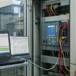
Relay testing and commissioning is the final engineering assurance stage before energization, where protection performance, wiring integrity, settings accuracy, and system readiness must be fully proven. In industrial power systems, even a correctly selected relay can become a major operational risk if trip paths, CT/VT circuits، logic mapping، or SCADA visibility are not validated through a disciplined commissioning workflow. This process helps prevent false trips, failure to trip, poor selectivity, and incomplete fault visibility after startup.
In this article, we explain the complete workflow, from preparation and secondary injection to trip-path verification, SCADA integration, documentation, and safe handover.
Relay Testing and Commissioning
Relay testing and commissioning is the process of verifying that the installed protection relay, its settings, its wiring, and its interaction with the wider electrical system all match the approved design and operate as intended. This is not only a relay check. It is also a wiring check, a logic check, a trip-path check, and a documentation check.
A complete commissioning scope usually aims to confirm:
- The relay is the correct model and firmware for the approved application.
- The installed settings match the approved protection study or settings file.
- CT, VT, binary input, and binary output wiring are correct.
- Trip and alarm logic operate as intended under approved test methods.
- SCADA, PLC, and local indications show the correct data and status points.
Commissioning should always be carried out under the project procedure, approved test sheets, and the asset owner’s operating requirements.
Read About: Types of Protection Relay in Power System (Full Guide)
Types of Relay Tests in Testing and Commissioning
Relay commissioning does not depend on one test only. A complete protection relay testing and commissioning process usually combines visual checks, settings verification, functional tests, and interface tests to confirm that the relay performs correctly in the installed system.
Common types of tests include:
| Test | Description |
|---|---|
| Visual and mechanical inspection | Inspection of the relay, panel, terminals, and labeling |
| Settings verification | Verification against the approved relay settings file |
| Wiring and continuity checks | Checks for CTs, VTs, inputs, outputs, and trip circuits |
| Secondary injection tests | Verify pickup values, timing, and protection functions |
| Primary injection tests | Testing the protection system with primary current |
| Logic and interlocking tests | Verification of programmable logic and interlocks |
| Trip circuit tests | Ensure correct tripping of circuit breaker |
| SCADA / Communication tests | Check communication signals, alarms, and status |
| Final functional tests | End-to-end system verification |
The exact mix of tests depends on the relay type, the protection function, the project scope, and the owner’s commissioning standard.
Read About: How to Fix Power Supply Relay Failure ?
Pre-Commissioning Preparations for Relay Testing
Preparation reduces commissioning delays because most field issues are easier to solve before live testing begins. Pre-commissioning should establish that the team has the correct documents, tools, test equipment, settings files, and safety approvals before any active test work starts. Good preparation also reduces the chance of incorrect tests or repeated site visits.
A practical preparation list often includes:
- Approved single-line diagram, schematic drawings, wiring diagrams, and terminal schedules.
- Latest approved relay settings file and logic description where applicable.
- Commissioning procedures, test forms, and sign-off sheets.
- Calibrated test equipment suitable for the relay type and test scope.
- Confirmed isolation, permits, access approvals, and switching status.
- Clear communication with operations, construction, and SCADA/PLC teams.
A relay should not be treated as ready for commissioning only because it is powered. Readiness depends on document control, safe access, and confirmation that the installation is complete enough for meaningful testing.
Step-by-Step Relay Commissioning Procedures
A structured sequence improves traceability and reduces the chance of missing a critical interface or protection function. Commissioning is usually stronger when the team follows a repeatable sequence rather than moving between tests in an unplanned way. That sequence may vary by project, but the core logic remains similar.
A practical step-by-step procedure often includes:
- Step 1: confirm relay identity, nameplate details, firmware, and approved settings version.
- Step 2: inspect panel condition, wiring, terminal tightness, labeling, and earthing condition.
- Step 3: verify CT, VT, and binary wiring against the approved diagrams.
- Step 4: upload or confirm the approved settings and logic configuration.
- Step 5: perform secondary injection and verify pickup, timing, and functional outputs.
- Step 6: check trip paths, alarm paths, and approved interlocking functions.
- Step 7: confirm SCADA/PLC integration points, measurements, status, and event visibility.
- Step 8: complete final records, punch items, and handover documentation.
Every completed step should leave a documented result. That record becomes part of the system evidence for energization and future maintenance review.
Relay Testing and Commissioning Checklist
Quick reference for engineers to verify relay readiness before energization:
- Verify relay model – confirm correct device and firmware for the application.
- Confirm settings file – ensure settings match the approved protection study.
- Check CT polarity – verify CT wiring and polarity match the design.
- Inject secondary current – confirm relay pickup and timing functions correctly.
- Verify trip path – ensure breaker trips correctly and trip circuit integrity.
- Confirm SCADA alarms – check alarms, measurements, and status points are accurate.
- Save disturbance records – record events for future review and troubleshooting.
Field Calibration and Adjustment Techniques
Field calibration or adjustment does not mean changing settings freely until the relay appears to work. In a protection system, adjustments should only be made where the approved settings, the measured field condition, or the commissioning evidence show that a correction is necessary.
Field adjustments may involve:
- Correcting communication parameters so SCADA or gateway points map correctly.
- Aligning time synchronization or event recording settings with project requirements.
- Updating logic mapping where installed field wiring differs from the approved drawing and formal approval has been obtained.
- Confirming output assignments, annunciation, or trip matrix details within the approved design scope.
Any adjustment must be recorded in the relay file history, the test documentation, and the project document control workflow. Unrecorded field changes create future protection risk.
Common Issues Encountered During Testing and Commissioning
Commissioning issues often come from drawings, wiring, settings, or interface mismatches rather than relay hardware alone. Protection relay commissioning often reveals issues that were not obvious during installation. These issues may come from construction, design revisions, communication mapping, or incomplete documentation.
Common issues include:
- CT polarity or ratio mismatch compared with the approved scheme.
- VT wiring errors or missing voltage references.
- Binary input or output wiring not matching the relay logic file.
- Trip circuit supervision alarms caused by incomplete breaker interface checks.
- SCADA or PLC points not aligned with the final relay configuration.
- Missing or outdated settings files after late engineering changes.
The correct response is to document the issue, identify the root cause, obtain approval where needed, and retest the affected functions after correction
Integration with SCADA and PLC Systems During Commissioning
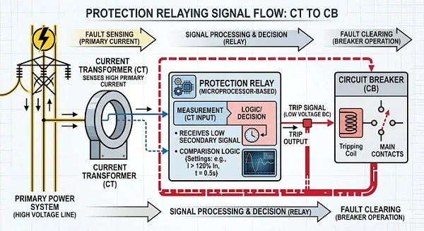
Commissioning is not complete if relay information and alarms are correct locally but incorrect in the supervisory systems. Modern relays often provide alarms, measurements, breaker status, self-supervision, and event indicators to SCADA, PLC, or gateway systems. That means commissioning must extend beyond local relay behavior and include the supervisory visibility layer.
Integration checks often include:
- Status point verification for breaker state, relay pickup, trip, and health alarms.
- Measurement checks for current, voltage, power, frequency, or other approved values.
- Event and alarm timing review where the site requires sequence accuracy.
- Confirmation that control and status authority boundaries are clear and documented.
- Validation that the final relay dataset matches the SCADA/PLC mapping list.
If integration is incomplete, operators may receive wrong information even when the relay itself is configured correctly. That is why integration testing is a commissioning requirement, not an optional extra.
Documentation and Reporting Best Practices
Commissioning quality depends heavily on documentation because future maintenance teams rely on those records. Good relay commissioning records help prove what was tested, what passed, what failed, what changed, and what remains open. Without that record, future troubleshooting becomes slower and coordination between teams becomes weaker.
Useful reporting practices commonly include:
- Using approved test sheets with test values, settings references, and signed results.
- Recording the settings file version used during final commissioning.
- Keeping punch lists and corrective actions linked to retest evidence.
- Saving final relay configuration files and event or disturbance records where relevant.
- Maintaining clear handover documents for operations and maintenance teams.
Documentation should be complete enough that another qualified engineer can understand the commissioned condition without relying on memory or informal notes.
Safety Measures During Testing and Commissioning
Safety controls matter because relay testing can influence tripping paths, breaker status, and protection availability. Testing should always be handled under the site’s approved electrical safety procedures. Testing is not only a technical task. It is a safety-critical activity because temporary changes, test injections, or trip-path verification can influence live or soon-to-be-energized equipment.
Important safety measures normally include:
- Follow permit, isolation, switching, and lockout/tagout requirements where applicable.
- Confirm the protection status before blocking, bypassing, or testing trip functions.
- Coordinate with operations before any test that may affect annunciation, interlocks, or breaker operation.
- Use approved test blocks, links, or isolation methods for CT, VT, and trip circuits.
- Restore all temporary changes and confirm final protection availability before handover.
A technically correct test that is performed without proper safety coordination can still create unacceptable operational risk.
Maximize Industrial Power System Reliability
Riyadh Al-Etqan Company (R-Aletqan) supports industrial electrical and automation projects by providing disciplined testing and commissioning, thorough documentation, and reliable system handover. By treating commissioning as a full engineering assurance process, the company ensures settings, wiring, interfaces, and protection response are verified, improving SCADA/PLC integration, logic accuracy, and overall system reliability.
A reliability-focused commissioning approach usually includes:
- Accurate preparation and document control before testing starts.
- A repeatable commissioning sequence with approved test sheets.
- Clear retesting after any correction or field adjustment.
- Verified integration with SCADA, PLC, and operator alarm visibility.
Complete final records for maintenance, audit, and future engineering review
Conclusion
Relay testing and commissioning should be treated as a structured assurance process that confirms settings, wiring, trip paths, communication points, and operational readiness before service. When commissioning is planned carefully, documented properly, and integrated with SCADA and PLC visibility, industrial power systems are better prepared to operate reliably and respond safely to faults.
To review our capability presentation and discuss your requirements, view the company presentation and contact Riyadh Al-Itqan Company to book a discussion and request a quotation. View the presentation
FAQ
Can relay miscoordination cause large-scale power outages?
Relay miscoordination can contribute to wider outages if protection zones do not operate selectively and faults are cleared by upstream devices unnecessarily. The severity depends on the network design, fault location, and how many sources or feeders are affected.
Which tests confirm proper relay operation before energizing?
Proper operation is normally supported by a combination of settings verification, wiring checks, secondary injection, logic verification, trip-path checks where approved, and confirmation of alarms, status, and measurements in the related supervisory systems.
Why do protection relays malfunction?
Protection relays may malfunction because of incorrect settings, wiring errors, CT or VT circuit issues, incomplete configuration changes, communication mapping problems, poor maintenance, or environmental stress. The correct cause should be confirmed through structured testing and review rather than assumption.