

A VFD replacement checklist is a structured record of the drive parameters, motor information, control settings, communication details, protection functions, and operating conditions that must be captured before removing an existing variable frequency drive. Electrical maintenance engineers, drive technicians, project engineers, and reliability teams use it to preserve the intended behavior of the motor system and prevent commissioning delays. Recording this information turns an emergency old drive replacement into a controlled engineering activity rather than a hardware swap based on assumptions.
Quick Answer: Why Is a VFD Replacement Checklist Important?
A VFD replacement checklist is important because the existing drive contains application-specific settings that may not be recoverable after removal. Motor nameplate data, control mode, ramp times, frequency limits, protection thresholds, digital and analog I/O assignments, communication parameters, and fault history all influence how the replacement operates. Factory defaults rarely represent the original application. Capturing the baseline before isolation allows the team to plan parameter migration, verify compatibility, perform safer drive commissioning, and investigate unexpected behavior with evidence instead of guesswork.
A replacement is therefore not only an exchange of power electronics. It is a controlled change to a motor-control system that may interact with PLC logic, HMI commands, interlocks, process instruments, and upstream protection. OEM guidance commonly separates motor data, ramps, speed limits, and command sources into distinct setup areas, which is why a structured record is more reliable than a single photograph of the keypad.[1] [2]
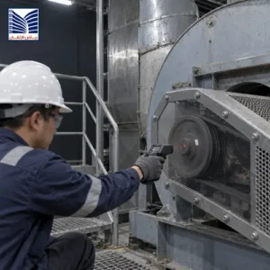
What Information Should Be Captured Before Removing an Existing VFD?
Capture the following 12 parameter groups while the old drive is still accessible and the motor system is in a known operating condition. Record the parameter number, value, units, source, and any relevant comment. If the replacement drive is from a different family, map each function rather than copying numbers blindly.
1. Motor Nameplate Data
Record rated voltage, full-load current, power, frequency, speed, and connection type. Note motor type, duty information, and star or delta wiring. Accurate motor data capture supports current monitoring, torque control, thermal protection, and autotune preparation.
2. Motor Control Mode
Identify V/F, sensorless vector, closed-loop vector, permanent-magnet, or another OEM-specific mode. Record encoder feedback, scaling, motor identification, and torque or speed selections. Control mode determines the migration map and commissioning tests; a different architecture may require engineering review instead of direct transfer.
3. Acceleration and Deceleration Settings
Capture acceleration/deceleration times, ramp shape, second-ramp and jog settings, emergency-stop behavior, S-curve, and quick-stop values. Also record coast, ramp, DC-injection, dynamic-braking, or externally controlled stopping. These settings affect current, mechanical stress, timing, and deceleration response.
4. Frequency Limits
Record minimum/maximum frequency, reference limits, skip frequencies, overspeed limits, base frequency, and application windows. Compare them with motor, gearbox or pump requirements, and interlocks. An expanded operating range can create mechanical, thermal, or process risk even when the motor starts normally.
5. Current and Protection Settings
Capture current limits, motor thermal current, overload class, stall prevention, underload/overload thresholds, phase-loss detection, voltage behavior, short-circuit protection, and restart settings. Record whether protection resides in the drive, thermistor, PLC, or external relay. Investigate faults before increasing thresholds.
6. Motor Autotune Data
Record whether autotune was completed, its mode and date, and whether the motor was coupled. Save exposed results, but do not assume they transfer between drive families: algorithms and motor models differ. Repeat the applicable identification procedure on the replacement according to the OEM manual.
7. Digital Input Configuration
Document digital input assignments for run, stop, direction, reset, jog, preset speed, enable, external fault, local/remote selection, and interlocks. Record logic, active state, delays, and terminals. A wiring diagram may not show parameterized input behavior.
8. Analog Input Scaling
Capture analog input source, signal type, range, scaling, offset, filtering, loss-of-signal response, and reference mapping. Note the process variable and whether the signal is 0–10 V, 4–20 mA, bipolar, PLC-supplied, or from an instrument loop. Incorrect scaling can make a wired replacement respond incorrectly.
9. Output Relay Configuration
Record each relay or transistor output function—ready, running, at speed, fault, warning, current limit, or threshold—along with normally open/closed wiring, logic, delays, and PLC destination. Changed relay behavior can create false permissives, missed trips, or misleading status.
10. Communication Settings
Record network address, protocol, baud rate, parity, data format, node identity, control/reference source, timeout, and fault response. Include Ethernet or serial settings, fieldbus mapping, registers, scaling, and command/status bits. VFD parameter transfer must preserve the PLC or supervisory interface contract.
11. Fault History and Alarm Records
Export or photograph recent faults, warnings, trips, frequency/current at fault, DC-bus conditions, operating hours, and reset history. This evidence can show whether failure originated in the motor, cable, load, cooling, supply, or controls. Preserve it before replacement.
12. Application-Specific Parameters
Capture application functions for pumps, fans, conveyors, hoists, compressors, mixers, positioning, PID, sleep/wake, flying start, brake control, multi-motor, and bypass arrangements. Record setpoints, recipes, permissives, interlocks, and external sequencing; these often sit outside the basic menu but control post-replacement behavior.
VFD Parameter Backup Before Replacement: Best Practices
A reliable VFD parameter backup uses multiple capture methods. Export the complete set through the keypad, software, memory device, or service tool when supported. Use a controlled filename containing asset, drive identity, date, and revision; preserve the original.
Save screenshots of critical parameter groups, nameplate data, terminals, fault history, and communication pages. Images supplement, but do not replace, a structured list. Record model, rating, firmware, asset identifier, options, motor cabling, and engineering-software version. Confirm compatibility with the motor, supply, braking equipment, enclosure, cooling, and control architecture; assess motor requirements against applicable standards.[3]
Maintain revision history showing who captured settings, whether they came from the live drive or offline file, changes made during testing, and the approved production revision. Store backups redundantly with controlled access.
Common Mistakes During VFD Replacement
Common mistakes include installing a new drive without recording settings, assuming factory defaults, ignoring motor data, omitting communications, failing to verify rotation, and skipping tests. Defaults may select local control, unsuitable limits, incorrect motor data, or a different stop response. Incorrect motor data can cause poor torque, nuisance trips, weak thermal protection, or failed autotune. Missing network mapping can make a healthy drive appear unavailable. Bench startup does not prove safe behavior under load, deceleration, or PLC control.
VFD Replacement Commissioning Checklist After Installation
After installation, use a staged commissioning sequence under the OEM manual, permit system, lockout/tagout procedure, and approved method statement. Electrical work must be performed by qualified personnel. OEM guidance commonly requires supply compatibility, grounding, controlled de-energization, and voltage-absence verification before work.[2]
| Stage | Verification |
|---|---|
| Mechanical inspection | Confirm mounting, ventilation, enclosure condition, cooling paths, clearances, motor coupling, guards, and braking components. |
| Wiring verification | Check supply, motor output, grounding, control wiring, shields, fuses or breakers, terminal torque, phase identification, and cable routing against approved drawings. |
| Parameter loading | Load the approved parameter set only after confirming drive model, firmware, option cards, motor data, and compatibility. Record any converted or manually entered values. |
| Motor rotation check | Use a safe, controlled test to confirm direction, start/stop behavior, and command source before coupling or full-load operation where the procedure requires it. |
| No-load test | Check current balance, acceleration, deceleration, speed feedback, noise, vibration, warnings, and stop behavior without process load when appropriate. |
| Load test | Run through the required operating range and observe current, torque, temperature, speed stability, process response, and mechanical behavior. |
| Alarm verification | Confirm expected fault, warning, external-trip, loss-of-reference, communication-loss, and reset responses without defeating safety functions. |
| Final documentation | Save the commissioned parameter file, updated drawings, test results, fault history, firmware, changes, approvals, and new baseline revision. |
During drive commissioning, compare behavior with the pre-removal record. If a fault occurs, also check motor insulation, cable, supply quality, mechanical load, cooling, grounding, and control signals. A VFD preventive maintenance checklist can help maintain the new baseline.
When Should Plants Replace Instead of Repair a VFD?
Choose repair or replacement using risk and lifecycle evidence, not only whether the drive powers up. Consider this framework:
| Decision factor | Questions to ask |
|---|---|
| Equipment criticality | How would failure affect safety, production, quality, utilities, or environmental control? Is a tested spare available? |
| Availability of spare parts | Are compatible power modules, control boards, fans, keypads, and option cards obtainable through an appropriate channel? |
| Age and condition | Is the drive near the end of its supported service life? Are cooling components, capacitors, or insulation showing deterioration? |
| Manufacturer support | Are manuals, firmware, diagnostic tools, and technical support available for the installed model? |
| Failure condition | Is the fault isolated and repairable, or is there evidence of thermal damage, repeated trips, DC-bus failure, or wider system damage? |
| Lifecycle considerations | Will repair preserve the required performance, communications, safety interfaces, and maintainability, or would a compatible replacement reduce technical uncertainty? |
A repair may be reasonable when the failure is understood, parts and expertise are available, and the restored unit can be tested. Replacement may be more appropriate when the unit is obsolete, repeatedly failing, incompatible with current control requirements, or difficult to validate. In either case, preserve the original parameters and fault evidence before work begins.
How Engineering Support Helps During VFD Replacement
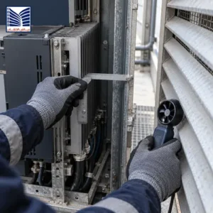
Engineering support can assess the failed drive, verify motor and application requirements, map old parameter groups to the replacement platform, and identify documentation gaps. It can review communication with the PLC, HMI, instrumentation, and protection equipment. A broader variable frequency drive solutions scope can coordinate migration, testing, and commissioning.
Support may include parameter extraction, compatibility review, controlled VFD parameter transfer, wiring checks, staged testing, fault analysis, and final documentation. If the drive is part of a machine sequence, programmable logic controller solutions may also be relevant because the PLC can define run commands, speed references, interlocks, permissives, and fault handling.
The goal is not simply to install a new drive. It is to preserve the motor-control intent, validate the interfaces, identify the cause of failure, and establish a documented operating baseline for future maintenance.
Frequently Asked Questions
What should be checked before replacing a VFD?
Check the old drive model, firmware, motor nameplate data, control mode, ramps, frequency limits, protection, I/O, relay functions, communications, fault history, and application functions. Inspect wiring, grounding, motor, cooling, braking equipment, and load. Save the live parameter set and operating state before isolation to guide hardware selection and commissioning.
Can VFD parameters be transferred to a new drive?
Sometimes, but transferability depends on drive family, software, firmware, option cards, motor-control algorithm, and parameter structure. A file from one model may not be accepted by another, and identical parameter numbers may represent different functions. Treat imported values as a starting point. Review motor data, control mode, protection, I/O, communications, and application functions manually, then test the replacement under an approved commissioning procedure.
Why is motor data important during VFD replacement?
Motor voltage, current, power, frequency, speed, and connection type are used by the drive for its motor model, current limits, thermal protection, and control calculations. Incorrect data can cause poor torque response, nuisance trips, inaccurate protection, or unsuccessful autotune. The values should be taken from the actual motor nameplate and confirmed against the motor wiring and the replacement drive’s permitted operating range.
What causes commissioning problems after VFD replacement?
Common causes include missing motor data, incompatible control mode, incorrect command or reference source, wrong acceleration or deceleration settings, faulty analog scaling, incomplete PLC mapping, incorrect network parameters, changed relay logic, and an unresolved mechanical or motor fault. Factory defaults can also create unexpected local control or limits. Compare the commissioned settings with the pre-removal record and investigate the complete electrical, mechanical, and control path.
Should VFD settings be backed up regularly?
Yes. Perform a VFD parameter backup before modifications, firmware updates, troubleshooting, planned shutdowns, or replacement, and create a new approved baseline after each documented change. Periodically verify that files open, required software and cables are available, and the stored revision matches the live drive. Keep parameter files, screenshots, drawings, fault records, and change history in controlled storage rather than relying on one technician’s computer.
What tests should be performed after installing a replacement drive?
Perform mechanical inspection, wiring and grounding verification, parameter loading review, motor rotation check, no-load testing, load testing, communication checks, alarm and fault-response verification, and final documentation. Observe current, speed, temperature, vibration, acceleration, deceleration, process response, and PLC command behavior. Use the OEM manual and site safety procedure, and do not return the equipment to normal operation until the responsible team accepts the test results.
Request VFD Replacement and Commissioning Support
Request a VFD replacement review, parameter migration assessment, testing, or commissioning support before removing an existing drive. A review can preserve motor data, control settings, communication mappings, fault evidence, and application parameters while identifying compatibility and safety requirements. Contact support through the VFD replacement support contact.
A well-maintained VFD replacement checklist helps plants approach industrial drive replacement with better documentation, controlled parameter migration, and evidence-based commissioning.

