
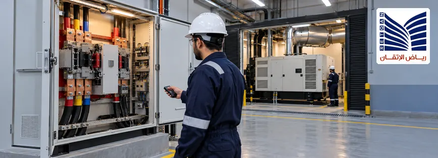
ATS panel functional testing verifies whether an Automatic Transfer Switch responds to the power-source conditions, control logic, interlocks, generator interfaces, alarms, and return-to-normal sequence defined in the approved project documents. Before handover, commissioning engineers should confirm that the tested functions behave as intended under the approved test conditions and that the results are documented. This requires more than checking the controller display: the team must evaluate relevant input signals, transfer commands, position feedback, and system indications. The test scope depends on the ATS design, source arrangement, generator configuration, OEM requirements, and site safety procedures.
Quick Answer: What Should ATS Panel Functional Testing Verify?
Before handover, engineers should verify the approved sequence of operation, source-sensing indications, transfer and retransfer behavior, applicable electrical and control interlocks, generator-start and availability interfaces where fitted, alarms, and relevant remote indications. The team should record the expected and actual results, test conditions, deviations, corrective actions, and retest evidence. Functional testing demonstrates the behavior of the functions tested under the documented conditions; it does not automatically prove every possible operating or failure scenario.
- Review the approved sequence of operation and test procedure.
- Confirm normal-source and alternate-source sensing.
- Verify transfer and return-to-normal logic.
- Check applicable interlocks and transfer permissives.
- Verify generator interfaces and failure responses where applicable.
- Check alarms, status indications, and remote signals.
- Document test results, deviations, corrective actions, and approvals.
All testing must follow the approved site procedures. Live switching requires the appropriate authorization and site-specific safety controls.
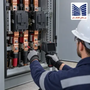
What Does ATS Panel Functional Testing Prove?
An Automatic Transfer Switch monitors the availability of designated electrical sources and controls the transfer of a load between them according to its configured operating philosophy. In a common standby-power arrangement, the ATS transfers a load from a normal utility source to an alternate source, such as a standby generator, when the approved transfer conditions are satisfied.
ATS functional testing evaluates whether the configured sensing, control, and indication functions respond as specified under the test conditions. Depending on the system, this may include source monitoring, transfer initiation, generator-start signaling, permissive logic, breaker or switch position feedback, alarms, and retransfer behavior.
Functional testing should be distinguished from other commissioning activities:
- Visual inspection: Checks equipment condition, identification, installation, and accessible connections.
- Component testing: Verifies individual devices or components within the approved test scope.
- Electrical acceptance testing: Assesses applicable electrical characteristics using the specified methods and acceptance criteria.
- Functional testing: Checks whether the control functions and interfaces behave as required.
- Operational testing: Evaluates system behavior under defined operating conditions, which may require separately authorized switching.
A successful functional test provides evidence about the functions and conditions actually tested. It does not guarantee uninterrupted power, prove every failure mode has been covered, or replace any separate inspection, electrical test, or acceptance requirement.
What Must Be Prepared Before ATS Commissioning?
Review the Approved Sequence of Operation
The approved sequence of operation should be the reference for the ATS commissioning checklist. It defines the conditions that initiate transfer, the permissives that must be satisfied, and the intended system response when a source becomes unavailable or returns.
Depending on the installation, the sequence may define:
- Normal and alternate power-source definitions.
- Source-availability criteria and monitoring functions.
- Transfer initiation conditions.
- Generator-start interfaces, where applicable.
- Transfer permissives and electrical or control interlocks.
- Return-to-normal conditions and retransfer logic.
- Generator cooldown or stop logic, where provided.
- Required alarms, status indications, and event records.
- Defined abnormal conditions and failure responses.
Do not substitute assumed voltage thresholds, frequency limits, time delays, or operating sequences for the approved requirements. Actual values and behavior must be established from the project documentation, ATS controller configuration, and applicable OEM instructions.
Confirm Test Preconditions and Responsibilities
Before testing begins, the responsible team should establish that the equipment, documentation, personnel, and test arrangements are suitable for the planned work.
- Confirm the approved test procedure and acceptance criteria.
- Review applicable power schematics, control drawings, and interface diagrams.
- Confirm relevant risk assessments, permits, and required authorizations.
- Define isolation boundaries and approved test arrangements.
- Obtain operational authorization for any switching that is required.
- Coordinate with facility operations and generator personnel.
- Confirm that test instruments are suitable and appropriately calibrated where required.
- Assign responsibility for execution, witnessing, recording, corrective actions, and approval.
Where a test could affect an energized system, standby-power availability, or protective functions, the method must be assessed and authorized before work starts. Do not bypass interlocks or introduce an actual source failure simply to force a test result.
Verify Source Sensing and Source Availability
Source sensing is a central part of automatic transfer switch testing because the controller must recognize the source conditions specified in its approved configuration. A controller display alone may not demonstrate that the complete sensing and control path behaves correctly.
Check Normal-Source Monitoring
Verify the applicable normal-source monitoring functions against the approved design. Depending on the ATS, these may include:
- Voltage monitoring.
- Frequency monitoring, where configured.
- Phase sequence or phase-condition monitoring, where applicable.
- Normal-source available and unavailable indications.
- Alarms associated with configured abnormal source conditions.
The test should establish that the relevant inputs and indications correspond to the approved test condition. The required parameters and limits vary by equipment and project; not every ATS monitors every listed condition.
Check Alternate-Source Monitoring
The alternate source must be recognized as available according to the approved transfer logic before the system proceeds with the relevant transfer sequence. In a generator-backed installation, review how the ATS interprets generator-start requests, generator-ready feedback, and any additional source-availability signals required by the design.
A single active status contact does not necessarily prove that the generator is suitable for transfer. The approved sequence may require several conditions or permissives to be satisfied. Verify the actual configured requirements rather than assuming that all generator-backed ATS systems use the same logic.
Test the Transfer and Return-to-Normal Sequences
Verify the Transfer Sequence
The transfer test should establish whether the ATS responds to the defined loss or unavailability of the normal source in accordance with the approved sequence. The exact test method depends on the installation, source arrangement, controller design, and site authorization.
Where applicable, review the following functions and associated evidence:
- Source recognition: Confirm that the specified source condition is represented correctly by the controller’s monitored inputs and status indications.
- Transfer initiation: Verify that the configured conditions for initiating transfer are evaluated as specified.
- Generator interface: Where applicable, confirm the generator-start request and the relevant feedback signals.
- Alternate-source availability: Confirm that the approved availability conditions and permissives are recognized.
- Transfer command: Verify the expected command and the corresponding status feedback using the approved test method.
- Alarms and records: Check relevant alarms, controller indications, and event records where these functions are included in the test scope.
This list is a functional review framework, not a universal live switching procedure. The actual sequence may differ depending on the ATS design, generator arrangement, transfer method, and project requirements.
Verify Retransfer to the Normal Source
Retransfer is the process of returning the load to the normal source when the approved conditions for doing so are satisfied. Commissioning should verify this behavior where automatic or manual retransfer is part of the specified system operation.
Depending on the configured system, the review may include:
- Recognition that the normal source has returned.
- Confirmation of the required source-availability conditions.
- Any specified qualification or stability period.
- Retransfer permissives and applicable interlocks.
- Transfer command and position feedback.
- Generator cooldown or stop logic, where provided.
Do not assume that every ATS automatically retransfers or shuts down a generator after the load returns to normal power. Verify the actual operating philosophy and record the observed behavior against the approved criteria.
Understand the Transfer Mode
ATS installations may use different transfer philosophies. The applicable arrangement must be identified from the approved design and equipment documentation.
- Open-transition transfer: The load is disconnected from one source before connection to the other source is completed, according to the equipment’s design.
- Closed-transition transfer: Where specifically designed and authorized, the transfer arrangement may briefly connect sources in parallel under defined conditions.
Not every ATS supports closed-transition operation. Any arrangement involving parallel sources requires the appropriate design provisions, protection, interlocking, synchronization requirements, and authorization. A generic commissioning checklist cannot establish that parallel operation is safe for a particular installation.
Verify ATS Interlocks and Generator Failure Scenarios
ATS Interlock Verification
Interlocks and transfer permissives help prevent prohibited switching actions and ensure that the system follows its approved operating philosophy. Their function and arrangement depend on the equipment design and the electrical scheme.
Where applicable, verify:
- Electrical and mechanical interlocks, where fitted.
- Transfer permissives and source-selection logic.
- Required prevention of conflicting source connections.
- Position feedback from the relevant switching devices.
- Consistency between control commands and equipment status indications.
- Required restrictions on unauthorized or conflicting switching.
The test must confirm the intended interlock behavior without defeating the safety function. If an interlock prevents an expected action, investigate the relevant permissives, signals, and approved logic instead of bypassing the interlock to obtain a pass result.
Generator-Ready and Fail-to-Start Cases
Where a standby generator is the alternate source, the approved test scope should identify how the ATS and generator controls interact when a start is requested and when the source becomes available—or fails to become available.
Depending on the design, relevant cases may include:
- A generator-start request and its associated indication.
- Generator-ready or source-available feedback.
- Failure to start or failure to become available within the specified sequence.
- Loss of the alternate source, where included in the approved test scope.
- Relevant alarms and status indications.
- The defined response when transfer conditions are not satisfied.
Use approved simulation facilities, designated test arrangements, or authorized operating procedures suitable for the installation. Do not create an actual supply failure, disable generator protection, or manipulate live equipment without an assessed and approved site-specific test plan.
Check Alarms, Indications, and Control Interfaces
Commissioning should verify that important ATS states are presented correctly at the controller and at any connected supervisory system included in the project scope. Depending on the design, these may include:
- Normal-source and alternate-source status.
- ATS position or transfer status.
- Transfer-in-progress indications.
- Source-failure alarms.
- Generator-start, generator-fault, or generator-availability indications.
- Failure-to-transfer alarms.
- Controller faults and relevant diagnostics.
- Remote indications and SCADA/HMI signals, where integrated.
Compare each indication with its corresponding controller status, approved signal list, or other relevant evidence. A displayed alarm does not independently prove that the intended physical action occurred; it proves only what the available indication supports.
Where supervisory monitoring is part of the installation, the SCADA and HMI monitoring systems page provides related context on industrial monitoring and control interfaces. Confirm the actual integration scope for the specific project.
What Records Should Be Included in the ATS Handover Package?
Commissioning records provide evidence of what was tested, under which conditions, and whether the observed behavior met the approved criteria. The handover package should reflect the project contract, document-control requirements, and the actual ATS configuration.
Functional Test Records
Where applicable, the test report should identify:
- Equipment and ATS controller identification.
- The approved test procedure and revision.
- Test prerequisites and conditions.
- The expected behavior and acceptance criteria.
- The actual observed behavior.
- Pass, fail, not tested, or other agreed status.
- Relevant measurements, indications, or supporting records.
- Deviations and corrective actions.
- Retest results following correction.
- Witness, reviewer, and approval details where required.
A test marked as passed should have supporting evidence for the function actually examined. A failed, excluded, or incomplete test must not be represented as a successful verification.
Drawings, Settings, and Configuration Records
The final documentation should include the applicable approved references, such as:
- Approved sequence of operation.
- Relevant control and power schematics.
- Applicable controller configuration or parameter records.
- Source-sensing and transfer-logic references.
- Generator interface documentation, where relevant.
- Approved change and revision records.
- Applicable OEM installation and operating manuals.
- Outstanding items and agreed limitations.
Documentation should reflect the installed and approved configuration. If changes were made during commissioning, their status and supporting evidence should be recorded under the project’s change-control process.
Test Sign-Off and Outstanding Issues
Before handover, distinguish between functions that passed, deviations that have been formally accepted, and items that remain unresolved. Record outstanding defects, excluded tests, corrective actions, responsible parties, and the agreed disposition in accordance with the project process.
Passing one functional test does not automatically mean that the panel is ready for unrestricted operation. Handover readiness depends on the complete agreed scope, relevant safety and acceptance requirements, and formal approval.
Common ATS Commissioning Mistakes
- Testing against an assumed sequence: The observed behavior may be judged against the wrong expectation. Use the approved sequence of operation as the reference.
- Checking only the controller display: A display may not prove that the input/output path or switching-device response is correct. Verify relevant signals and feedback using the approved method.
- Overlooking source-sensing logic: Incorrect or incomplete source indications can invalidate later conclusions. Check the applicable sensing functions and their defined criteria.
- Ignoring retransfer behavior: A system may be tested for transfer but not for its specified return-to-normal behavior. Include retransfer where required by the approved scope.
- Missing generator failure scenarios: Generator-start and availability interfaces may remain unverified. Identify the applicable failure responses in the approved test plan.
- Assuming all ATS systems are identical: Transfer modes, delays, thresholds, and generator interfaces vary. Follow the installed controller documentation and project requirements.
- Bypassing an interlock: This can conceal a logic or permissive problem and undermine safe testing. Investigate the cause and use only approved test arrangements.
- Performing live switching without authorization: This introduces operational risks. Obtain the required switching authorization and apply the site-specific safety controls.
- Recording incomplete test results: Results without test conditions or acceptance criteria are difficult to evaluate. Record the expected and actual behavior.
- Treating an incomplete test as a pass: Untested functions remain unverified. Mark them clearly and obtain an approved disposition.
- Assuming an alarm proves a physical action: An indication may represent a command or status signal rather than confirmed equipment operation. Correlate it with appropriate feedback.
- Making undocumented configuration changes: Unrecorded changes undermine traceability. Apply the required approval, revision control, and retesting process.
Safety Boundaries During ATS Functional Testing
Functional verification and authorization for live switching are different matters. A test plan must identify which checks can be completed using approved simulation or isolated test arrangements and which require interaction with energized equipment or operational switching.
- Follow approved site safety procedures, permits, isolation requirements, and switching instructions.
- Obtain the necessary operational authorization before changing source or switching-device states.
- Confirm the test boundary, responsibilities, and expected system impact.
- Use approved isolation, verification, and test arrangements.
- Do not bypass protective devices or interlocks to force an expected result.
- Do not introduce a real source failure solely to test a sequence unless it has been assessed, approved, and arranged under site procedures.
- Apply additional engineering review to closed-transition or parallel-source arrangements where relevant.
- Stop and escalate if the observed behavior differs materially from the approved sequence or a safe test condition cannot be established.
No single test method is appropriate for every ATS installation. The equipment design, approved procedure, source arrangement, operating risks, and site requirements determine the appropriate test approach.
When Is Additional Engineering Support Needed?
A more detailed engineering review may be appropriate when commissioning or maintenance teams encounter:
- Unexpected transfer or retransfer behavior.
- Repeated ATS alarms.
- Unclear source-sensing indications.
- Missing or incorrectly interpreted generator-ready feedback.
- Failure-to-start or failure-to-transfer conditions.
- Differences between controller indications and actual equipment status.
- Unresolved interlock or permissive issues.
- Missing or outdated control drawings.
- Incomplete commissioning records.
- Unclear interfaces with protection relays or generator controls.
- A planned retrofit or modification to an existing ATS panel.
The next step depends on the evidence. It may involve reviewing the approved sequence, checking the relevant control interfaces, reconciling documentation, or defining an additional approved test. A problem does not automatically require a retrofit, and the appropriate service scope should be confirmed for the installation.
Where protection interfaces are relevant, the protection relay systems page provides related information about protection equipment, coordination, testing, and commissioning. Where generator synchronization or excitation interfaces are genuinely part of the design, consult the generator synchronization and AVR systems page. Not every ATS installation requires generator synchronization or parallel operation.
Discuss ATS Panel Requirements and Commissioning Scope
For commissioning engineers, maintenance teams, facility managers, and EPC contractors, a useful technical discussion should establish the actual application and the evidence required before handover.
Relevant information may include:
- The ATS application and normal/alternate source arrangement.
- Existing or proposed panel details.
- The approved sequence of operation.
- Required transfer and retransfer behavior.
- Generator interface requirements, where applicable.
- Interlocks and protection interfaces.
- Required functional test evidence and handover documents.
- Known functional issues or documentation gaps.
The LV/MV switchgear and ATS-related solutions page lists ATS panel design, supply, and retrofit alongside switchgear installation, testing, and commissioning services. The precise scope required for a specific project should be confirmed before work is agreed.
If you are preparing for ATS panel handover or reviewing an existing transfer system, discuss your ATS panel requirements and commissioning scope to establish the relevant technical checks, documentation, and project-specific acceptance criteria.
Frequently Asked Questions
1. What Is ATS Panel Functional Testing?
ATS panel functional testing verifies whether the transfer switch’s configured sensing, control logic, interlocks, indications, and interfaces behave according to the approved sequence under the conditions tested. Depending on the installation, this may include source availability, generator-start signaling, transfer, retransfer, alarms, and position feedback. The test scope depends on the ATS design, source arrangement, OEM requirements, and project acceptance criteria. A passed functional test does not prove every possible operating or failure condition.
2. What Should Be Checked Before ATS Commissioning?
Before commissioning, review the approved sequence of operation, test procedure, acceptance criteria, relevant electrical and control drawings, risk assessment, permits, and required authorizations. Confirm the test arrangements, suitable equipment, personnel responsibilities, and coordination with facility operations and generator teams where applicable. The team should also establish the source-sensing requirements, transfer logic, interlocks, generator interfaces, and required handover evidence. Actual test conditions must follow the approved procedure and site safety requirements.
3. What Is the Difference Between ATS Transfer and Retransfer?
Transfer moves the load from the normal source to an alternate source when the approved conditions for doing so are satisfied. Retransfer returns the load to the normal source when the required return conditions are met. Depending on the design, the system may use automatic or manual retransfer and may include specific source qualification, permissive, or generator-stop logic. Engineers should verify the actual operating philosophy rather than assume every ATS provides automatic retransfer.
4. How Do You Verify an ATS Generator-Start Sequence?
Verify the generator interface against the approved sequence and applicable controller documentation. Where included in the test scope, review the start request, generator-ready or source-available feedback, required permissives, associated alarms, and the defined response if the generator does not become available. Use approved simulation, test facilities, or authorized operating procedures. Do not create an actual source failure or disable generator protection without a site-specific test plan and the required authorization.
5. Why Is ATS Interlock Verification Important?
Interlock verification helps establish that the ATS follows its approved switching restrictions and prevents prohibited or conflicting operations where the design requires it. Checks may include electrical or mechanical interlocks, transfer permissives, source-selection logic, position feedback, and consistency between commands and status indications. The exact arrangement depends on the installed equipment. An interlock should never be bypassed simply to obtain a passing test result; unexpected behavior should be investigated through the approved procedure.
6. What Happens If a Standby Generator Fails to Start During an ATS Test?
The expected response depends on the approved sequence, generator controls, ATS design, and available alternate sources. The test should establish how the system indicates the failure, whether transfer permissives remain unsatisfied, and what alarms or subsequent actions are specified. The team should document the observed result and follow the approved operating and troubleshooting procedures. A generator failure should not be handled by bypassing protection or forcing a transfer outside the authorized test plan.
7. What Records Should Be Included in an ATS Commissioning Handover?
The handover package should include the applicable approved test procedure, equipment identification, test conditions, expected and actual results, test status, deviations, corrective actions, retest evidence, and required approvals. Relevant supporting documents may include the approved sequence of operation, control and power schematics, controller configuration records, generator interface documentation, OEM manuals, and outstanding-item registers. The exact deliverables depend on the project contract, approved document-control process, and installed system.
8. Can ATS Functional Testing Be Performed Without Live Switching?
Some functions may be checked using approved simulation, isolated test arrangements, or controller test facilities, depending on the equipment and test objective. However, these methods may not prove every physical switching action or operational interface. Any live switching or interaction with energized equipment requires the appropriate site-specific risk assessment, authorization, and approved procedure. The test plan should clearly identify what was verified, what was not tested, and whether further authorized testing is required.
Conclusion: Verify the Approved Sequence Before Handover
Effective ATS panel functional testing is an evidence-based commissioning activity. It verifies the applicable source-sensing functions, transfer and retransfer logic, interlocks, generator interfaces, alarms, and feedback against the approved operating sequence. The value of the test depends on clearly defined acceptance criteria, suitable test arrangements, accurate records, and formal treatment of outstanding issues.
Before handover, confirm that the documented results match the functions actually tested and that any deviations or exclusions have been addressed through the project’s approved process. Do not assume that a controller indication alone proves physical equipment behavior or that one successful test establishes complete operational reliability.
To discuss your ATS panel requirements and commissioning scope, visit the LV/MV switchgear and ATS-related solutions page or contact the engineering team to clarify the relevant technical checks, documentation, and project-specific acceptance criteria.