
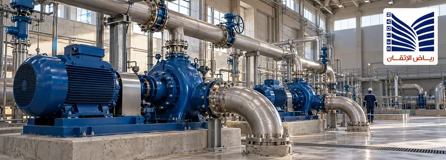
Choosing between VFD bypass vs standby drive requires more than comparing two backup options. A VFD bypass may provide an alternative supply path for a compatible motor, but normal variable-speed control may no longer be available. A standby-drive strategy may retain drive-based control through an alternative drive arrangement, depending on the design. For a critical pump, the correct choice depends on the required flow and pressure, motor characteristics, operating limits, protection and interlocks, control-system integration, and acceptable recovery time. Neither approach automatically guarantees uninterrupted operation or the required process duty, so the application must be evaluated before selecting an architecture.
What Is the Difference Between VFD Bypass and a Standby Drive?
What Is a VFD Bypass Arrangement?
A VFD bypass arrangement provides an alternative electrical path that allows a compatible motor to operate without normal power conversion through the variable frequency drive. In a typical line-bypass arrangement, the motor may receive power directly from the supply through an engineered switching and protection arrangement.
Bypassing the VFD can change the motor’s operating conditions. Depending on the design, the motor may operate at a speed primarily determined by supply frequency, motor characteristics, and load rather than the commanded variable speed normally provided by the drive.
Before selecting a VFD bypass panel, engineers should consider:
- Whether the motor can operate within its permitted limits in bypass mode.
- Whether the pump can deliver the required flow and pressure without normal VFD speed regulation.
- Whether the electrical supply can accommodate the applicable motor-starting conditions.
- Whether the protection, switching devices, and electrical interlocks suit the intended arrangement.
- Whether operators can identify bypass status and understand the changed operating limitations.
Bypass operation does not necessarily mean automatic transfer, uninterrupted operation, or continued process control. Some systems require a planned interruption and an approved recovery procedure. Others may provide designed automatic functions, but their behavior must be verified against the actual equipment and control philosophy.

What Is a Standby or Redundant Drive Strategy?
A standby-drive strategy provides an alternative drive capability, but the term can describe several different architectures. The design should clearly identify which arrangement is intended.
- Spare VFD: A replacement drive is held in inventory and installed when required. This supports recovery planning but does not necessarily provide immediate changeover.
- Alternative or redundant drive path: A specifically engineered arrangement provides an alternative drive capable of serving the required motor or load under defined conditions.
- Standby pump with its own drive: A separate pumping unit provides an alternative process path. This is equipment redundancy, not simply a redundant VFD for the same motor.
These options are not interchangeable. A spare drive may require installation, configuration, verification, and an interruption before the pump returns to service. An engineered redundant-drive arrangement may offer a different recovery path, while a standby pump can provide process redundancy if the hydraulic system, isolation arrangements, and controls support it.
Engineers must verify drive and motor compatibility, switching architecture, fault isolation, protection, control interfaces, and the approved recovery procedure. A replacement VFD must never be assumed compatible simply because its nominal power rating appears suitable.
When Does a Critical Pump Need a Bypass or Standby-Drive Strategy?
Define the Consequences of Losing the Pump
The first decision is how the process responds if the pump or its drive becomes unavailable. The required solution may differ significantly between a pump with adequate process buffering and a pump that supports an essential utility or continuous production operation.
Start by establishing:
- Whether loss of the pump interrupts production or an essential utility.
- Whether the process has sufficient buffer capacity to tolerate a temporary interruption.
- How long the process can remain without the required flow or pressure.
- Whether a separate standby pump is available.
- What recovery time is acceptable.
- Whether reduced-capacity operation is acceptable during recovery.
- Which operating conditions must be maintained after a drive fault.
These questions define the required availability strategy. A bypass may be worth evaluating where an approved alternative operating mode is acceptable. A redundant drive or standby pump may warrant consideration when preserving process performance is more important than simply providing a way to run the motor.
Determine Whether Fixed-Speed Operation Is Acceptable
Bypass operation may be unsuitable when the pump must maintain variable-speed control to satisfy process requirements. The motor might run successfully, yet the pump may not operate at the required duty point.
Review the applicable:
- Required flow and differential pressure.
- Minimum and maximum operating conditions.
- Pump performance characteristics and system curve.
- Minimum-flow requirements and permitted operating envelope.
- Potential hydraulic transients during a change in operating mode.
- Process-control stability and equipment limitations.
The actual pump, motor, and process documentation must establish whether the proposed bypass mode is acceptable. No single pump type or general rule establishes suitability for every installation.
Determine the Required Recovery Strategy
The recovery plan should distinguish between temporarily operating in a restricted mode, restoring the existing drive, transferring to a pre-engineered alternative drive path, and transferring process duty to a separate standby pump.
Each option has different equipment, control, maintenance, and verification implications. The selected strategy should be based on the plant’s process requirements, electrical design, safety controls, and reliability objectives.
VFD Bypass vs Standby Drive: Key Engineering Differences
| Evaluation factor | VFD bypass | Standby or redundant-drive strategy |
|---|---|---|
| Primary objective | Provide an alternative motor operating path that avoids normal VFD operation. | Provide alternative drive capability, depending on the architecture. |
| Variable-speed control | May be unavailable in bypass mode. | May be retained if the standby arrangement supports it. |
| Motor starting | Depends on the bypass design and supply arrangement; line starting may apply. | Depends on the standby-drive and switching architecture. |
| Pump operating point | Must be assessed for the intended bypass operating conditions. | Must be assessed for the intended standby operating mode. |
| Fault recovery | Depends on fault isolation and the approved bypass procedure. | Depends on alternative-drive availability, switching design, and recovery logic. |
| Protection and interlocks | Must address the bypass circuit and prevent incompatible switching states. | Must address drive selection, fault isolation, motor connection, and switching states. |
| Control integration | May require bypass-mode indications and different control behavior. | May require drive-selection logic, status feedback, and changeover coordination. |
| Maintenance | Includes the drive, bypass equipment, switching devices, and associated protection. | Includes the relevant drives, switching architecture, controls, and redundancy equipment. |
| Main limitation | Bypass may not preserve the required speed control or process duty. | Redundancy does not automatically guarantee immediate transfer or uninterrupted operation. |
This comparison is conceptual, not a substitute for detailed design. The actual performance and recovery capability depend on the approved electrical and process architecture, the equipment selected, and the operating procedures.
Motor and Pump Requirements That Influence the Decision
Motor Starting and Electrical Compatibility
Motor and supply characteristics influence whether bypass operation is practical. Starting a motor through a VFD can produce different electrical and mechanical conditions from starting it directly from the supply. A bypass arrangement that uses line starting may introduce higher starting current and voltage-dip considerations than normal drive-controlled starting.
Before approving a proposed arrangement, review:
- Motor nameplate data, rated voltage, frequency, power, and current.
- Motor starting method and permissible starting conditions.
- Drive and motor compatibility for the intended operating modes.
- Available electrical supply capacity.
- Relevant motor and drive protection requirements.
- OEM limitations and the approved electrical design.
Do not assume that all bypass panels use the same starting method or that a supply can accommodate the motor’s starting demand without further assessment.
Where motor specifications are central to the decision, review the relevant industrial electric motors information and the actual motor documentation.
Pump Duty and Process Constraints
The pump must be evaluated as part of the complete hydraulic system. Relevant factors include the required flow, differential pressure, expected operating range, pump and motor compatibility, system curve, minimum-flow limits, speed restrictions, and process stability.
Changing from variable-speed operation to bypass operation can change the pump operating point. Whether that change is acceptable depends on the actual equipment and process requirements, not simply on whether the motor can run.
Review applicable pump performance data and OEM operating limits before treating bypass as an acceptable fallback mode.
What Happens to Process Control in Bypass Mode?
Bypass operation may remove the VFD’s normal speed-control capability. Depending on the installation, this can affect flow regulation, pressure control, process response, minimum-flow management, PLC commands, drive-status feedback, and alarm handling.
The control philosophy should identify how the system behaves in each permitted mode, which commands remain available, which functions are restricted, and how operators are informed of the change. The control response must be designed and verified for the actual application; normal VFD performance should not be assumed to remain available in bypass.
Protection, Interlocks, and Changeover Requirements
The switching and protection architecture is central to both options. The design must address the permitted operating states and prevent incompatible source connections.
Depending on the installation, the engineering review may cover:
- Motor and drive protection.
- Short-circuit and overload protection.
- Drive-fault isolation.
- Electrical and mechanical interlocking.
- Prevention of incompatible supply connections.
- Breaker or contactor status feedback.
- Bypass-mode indications and alarms.
- Control-system permissives.
- Restart and recovery requirements.
- Behavior during an unsuccessful changeover.
Switching devices must be arranged so that the VFD output cannot be unintentionally connected to an alternative supply path. The actual design must follow the drive manufacturer’s instructions and the approved circuit arrangement.
Do not bypass interlocks, defeat protection, or perform live switching outside an approved procedure to test a proposed operating mode. Protection settings and switching requirements must be established for the actual equipment and application.
PLC and Control-System Integration
The electrical architecture and control-system logic must agree on the permitted operating modes. Where a PLC or other supervisory controller is involved, relevant interfaces may include:
- Run and stop commands.
- Speed references where supported.
- Drive-ready and drive-fault status.
- Bypass-mode indication.
- Selected-drive status.
- Motor-running feedback.
- Alarm and event reporting.
- Interlocks and permissives.
- Approved recovery or restart logic, where applicable.
- Operator visibility and control ownership.
The control logic should reflect the installed electrical arrangement and the approved sequence of operation. A PLC command or status indication is not a substitute for electrical protection or switching interlocks.
Where changes to control logic or interface signals are required, consult the relevant programmable logic controller solutions information and the approved project documentation. Not every bypass or standby-drive arrangement requires a PLC modification.
Maintenance, Testing, and Recovery Planning
Maintenance Considerations
The selected strategy must remain maintainable throughout the equipment lifecycle. Review access to drive and switching equipment, isolation requirements, spare-drive availability, replacement compatibility, configuration records, inspection needs, and responsibility for restoring the normal operating mode.
Maintenance planning should also establish which equipment can be tested during planned outages, which records must be retained, and how a replacement or repaired drive will be verified before returning to service. Inspection and maintenance intervals must follow the relevant OEM documentation and site-approved maintenance programme.
Functional Testing and Recovery Evidence
An approved test plan should verify the functions relevant to the selected architecture. Depending on the installation, evidence may cover:
- Normal VFD operation.
- Bypass-mode indications and control behavior.
- Drive-fault detection and status feedback.
- Switching and interlock functions.
- Alternative-drive selection or recovery logic.
- PLC and operator-interface indications.
- Alarm and event records.
- Restoration of the intended normal operating mode.
- Outstanding defects and corrective actions.
Simulated functional tests should be distinguished from tests conducted on the actual process system. All testing must follow the applicable OEM instructions, approved acceptance requirements, and site safety controls. This guide does not establish a universal live changeover or motor-reconnection procedure.
How to Choose the Right Strategy: An Engineering Decision Framework
Use the following framework to structure an initial engineering review before requesting a design proposal.
- Define process criticality. Establish the consequences of pump unavailability and the acceptable recovery time.
- Confirm the required pump duty. Identify flow, pressure, speed-control, and operating-envelope requirements.
- Assess bypass suitability. Determine whether the motor and pump can meet the required duty in the proposed bypass mode.
- Define the availability strategy. Decide whether the requirement is a restricted operating mode, an alternative drive path, or a separate standby pump.
- Review electrical compatibility. Confirm motor data, supply capacity, starting conditions, and equipment compatibility.
- Review protection and interlocks. Confirm that the switching arrangement supports the approved operating modes.
- Review control integration. Identify required PLC signals, alarms, feedback, and operator indications.
- Assess maintenance and recovery. Establish how the system will be tested, maintained, and restored to its intended operating state.
- Document the decision. Record assumptions, limitations, required tests, and outstanding engineering questions.
Preliminary Decision Matrix
| Application condition | Option to evaluate | Key verification |
|---|---|---|
| A suitable alternative motor operating mode is acceptable. | VFD bypass arrangement. | Confirm motor-starting conditions, pump duty, protection, and permitted bypass operation. |
| Variable-speed control remains important during drive-related recovery. | Standby or redundant-drive architecture. | Confirm drive compatibility, alternative power path, control integration, and recovery behavior. |
| The process requires an alternative pumping unit. | Standby pump with its own drive. | Confirm hydraulic capacity, isolation arrangements, control logic, and process transfer requirements. |
These are preliminary engineering considerations, not automatic design recommendations. The appropriate solution must be determined from the actual application and approved design requirements.
Common Mistakes When Selecting a VFD Bypass or Standby Drive
- Assuming bypass guarantees uninterrupted operation: The transition may require an interruption or an approved recovery procedure. Define the expected operating sequence and acceptable interruption.
- Assuming the pump will meet its required duty in bypass: Fixed-speed operation may produce a different flow or pressure. Assess the pump operating point and permitted operating envelope.
- Confusing a spare VFD with a standby pump: These provide different forms of redundancy. Document which equipment and process path are actually available.
- Ignoring motor-starting conditions: Bypass starting may impose different demands on the electrical supply. Review motor data and supply capacity.
- Overlooking protection and interlocks: An unsuitable switching arrangement can create incompatible operating states. Review the approved circuit and interlocking philosophy.
- Assuming normal speed control remains available in bypass: Some process functions may no longer operate as intended. Document mode-specific limitations and operator actions.
- Ignoring PLC feedback and alarms: Operators may lack a clear indication of the selected mode or drive status. Review relevant control-system interfaces.
- Selecting redundancy without defining recovery time: A spare drive may require installation and verification. Define the recovery objective and the resources needed to achieve it.
- Failing to document permitted operating modes: Unclear procedures can lead to incorrect assumptions. Record the approved modes, limitations, and responsibilities.
- Assuming compatibility without OEM review: Similar ratings do not establish full compatibility. Verify the actual motor, drive, switching design, and applicable documentation.
What Information Should Engineers Prepare Before an Application Review?
Preparing the relevant data helps establish whether a proposed critical pump drive strategy is suitable and which further engineering checks may be needed.
- Pump duty and process requirements.
- Pump and motor nameplate data.
- Existing VFD model and relevant technical documentation.
- Electrical supply characteristics and available capacity.
- Existing single-line diagrams and control drawings.
- Existing bypass or standby architecture, if applicable.
- Required operating modes and speed-control requirements.
- Acceptable process interruption and recovery time.
- Protection and interlocking requirements.
- PLC and control-system interface requirements.
- Relevant fault history if the review follows a drive failure.
- Applicable OEM limitations and project specifications.
This information supports the initial review but does not replace a site assessment, detailed engineering study, or equipment-specific compatibility checks where these are necessary.
How VFD and Motor Engineering Support Helps Improve Application Decisions
A structured application review can help clarify equipment requirements, identify missing information, and establish the technical limitations of a proposed bypass or standby-drive strategy.
Depending on the confirmed project scope, relevant review activities may include examining motor and drive compatibility, assessing the intended operating mode, reviewing protection and interlocking requirements, identifying control-integration needs, and clarifying maintenance and recovery considerations.
R-Aletqan’s published variable frequency drive solutions page describes LV and MV drives, AC and DC drives, and applications including pumps and fans. Its industrial motor information also covers motor supply and maintenance offerings. The suitability of a specific bypass panel or redundant-drive architecture must still be confirmed against the actual application and agreed scope.
Request an Application Review for a Critical Pump or Drive Installation
The appropriate choice between VFD bypass and a standby-drive strategy depends on the required pump duty, motor characteristics, permitted operating modes, protection design, control integration, and required recovery behavior. A technical review should establish these factors before a solution is selected.
If you are evaluating a critical pump drive strategy, prepare the available motor data, pump duty, existing drive arrangement, and required operating conditions. Review the published variable frequency drive solutions and industrial electric motor information as relevant starting points.
Request an application review for a critical pump or drive installation to discuss the required technical information, operating modes, protection interfaces, and verification scope.

Frequently Asked Questions
1. What Is the Difference Between a VFD Bypass and a Standby Drive?
A VFD bypass provides an alternative motor supply path that avoids normal VFD operation, potentially removing variable-speed control. A standby-drive strategy provides alternative drive capability, depending on the architecture. A spare drive that must be installed is different from an engineered redundant-drive path, and both differ from a standby pump with its own drive. The right option depends on the required pump duty, control needs, electrical design, and recovery objective.
2. Can a Pump Continue Operating if Its VFD Fails?
It may be possible if the installation has a suitable bypass arrangement, a compatible alternative drive path, or a separate standby pump. However, continued motor operation does not prove that the pump can meet the required flow and pressure. The available recovery method depends on the equipment, switching architecture, protection, control logic, and approved operating procedures.
3. Does VFD Bypass Allow a Pump to Maintain Variable-Speed Control?
Typically, bypass operation removes the normal VFD speed-regulation function because the motor operates through an alternative supply path. The resulting speed and pump operating point depend on the supply, motor, load, and system characteristics. Engineers should verify whether the resulting flow and pressure remain acceptable before treating bypass as a suitable operating mode.
4. When Should Engineers Consider a Redundant VFD?
A redundant-drive arrangement may warrant evaluation when the process needs an alternative drive capability and retaining drive-based speed control is important during recovery. Engineers should establish the required recovery time, drive and motor compatibility, switching arrangement, protection, and control interfaces. Redundancy does not automatically provide immediate transfer or uninterrupted operation; the actual architecture must be verified.
5. What Should Be Checked Before Selecting a Bypass Panel for a Critical Pump?
Review the motor’s nameplate data, supply capacity, starting conditions, pump duty, permitted operating modes, protection, switching interlocks, and control-system interfaces. Confirm whether the pump can operate within its required limits without normal variable-speed regulation. The bypass-panel design and acceptance requirements must be checked against the relevant OEM documentation and approved project design.
6. How Do Protection and Interlocks Affect VFD Bypass Operation?
Protection and interlocks help ensure that the switching arrangement operates only in permitted states and that the motor, drive, and alternative supply paths are appropriately isolated. The design must prevent incompatible source connections and provide relevant status feedback and fault handling. Actual protection and interlocking requirements depend on the circuit architecture, equipment, and approved engineering design.
7. Does a Standby Drive Guarantee Uninterrupted Pump Operation?
No. A standby drive can provide an alternative recovery capability, but transfer may depend on fault isolation, switching design, controller logic, equipment availability, and the approved operating procedure. Some arrangements require an interruption before the alternative drive is available. The expected recovery time and operating behavior must be established and verified for the actual installation.
8. What Information Is Needed to Evaluate a Critical Pump Drive Strategy?
Prepare the pump duty, motor nameplate data, existing VFD details, electrical supply information, single-line and control diagrams, permitted operating modes, protection and interlocking requirements, PLC interfaces, and acceptable recovery time. Relevant fault history and OEM limitations are also useful. This information supports the initial review but may not replace a site assessment or detailed engineering study.