
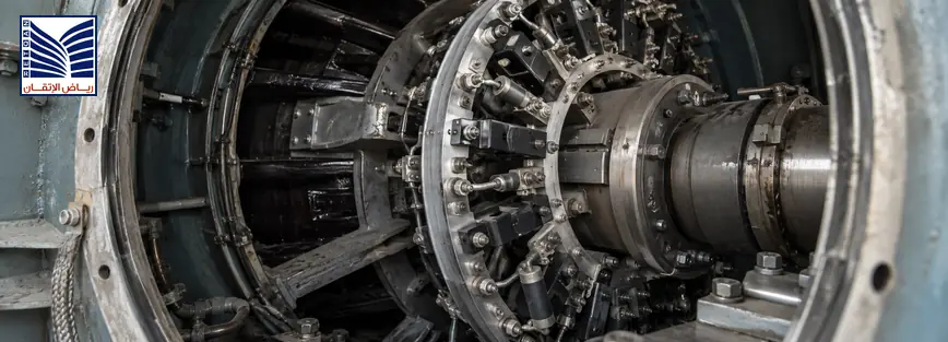
Generator load sharing problems occur when paralleled generator sets do not distribute active power (kW) or reactive power (kVAR) according to the intended control strategy. The cause may be a governor response mismatch, AVR or excitation issue, CT/PT feedback error, synchronization-controller configuration, communication fault, or measurement problem. Power-generation engineers, commissioning teams, and electrical maintenance managers should identify the affected control loop before changing settings. A structured diagnosis protects against unstable operation, nuisance protection trips, incorrect parameter changes, and repeated commissioning delays.
Quick Answer: Why Do Generator Load Sharing Problems Happen?
Generator load sharing problems happen when the controls that regulate mechanical power, excitation, measurement, or coordination do not agree. A kW imbalance usually points toward the prime mover, governor, speed/frequency response, load-sharing signal, or controller logic. A kVAR imbalance more often involves the AVR, excitation system, voltage reference, reactive-current feedback, or phase relationships. Control-loop interaction, incorrect CT/PT signals, controller communication loss, and scaling errors can affect both. Record operating data and alarms first, then isolate one loop at a time before modifying parameters.
In a correctly engineered parallel system, the generator controllers, governors, AVRs, protection functions, and measurements work as an integrated control system. Manufacturer documentation should take precedence over generic adjustment advice.[1] [2]
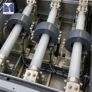
Understanding Generator Load Sharing: kW vs kVAR
Active Power Sharing (kW)
Active power is the real electrical power delivered to the load. In a conventional generator set, the prime mover—engine, turbine, or another mechanical source—supplies mechanical torque to the alternator. The governor regulates speed or fuel input, while the electrical system determines the relationship between speed and frequency. In parallel operation, the load-sharing controller modifies the governor reference so each unit contributes an intended portion of the total kW.
A unit that carries too much kW may have a higher governor reference, excessive fuel command, incorrect droop, or a biased load-sharing signal. A unit that carries too little may have limited actuator travel, slow response, an incorrect control mode, or a measurement problem. Equal kW is not always the correct objective: proportional sharing may be based on generator ratings, operating limits, or a configured dispatch strategy. Confirm the intended philosophy before calling a difference a fault.
Reactive Power Sharing (kVAR)
Reactive power supports magnetic fields and voltage regulation in an AC system. Its distribution between paralleled alternators is influenced by AVR output, excitation, voltage reference, droop or cross-current compensation, generator impedance, and reactive-current measurement. A kVAR-sharing problem can therefore exist even when kW sharing appears stable.
If one generator supplies excessive kVAR, its voltage reference or excitation response may be higher than the other units, or the feedback and compensation circuits may be mismatched. Low or unstable reactive sharing can also result from incorrect CT/PT phase identification, scaling, wiring, or controller configuration. The active and reactive loops should be analyzed separately before making a common adjustment.
A technical reference on paralleling dissimilar generators distinguishes kW load sharing from kVAR load sharing and relates real-power behavior to speed control and reactive-power behavior to voltage control.[1]
Common Causes of Generator kW Load Sharing Problems
Governor Control Issues
Governor problems include unequal droop settings, different gain or response times, actuator limits, speed-sensor issues, fuel-system constraints, and mismatched isochronous or droop modes. Check the speed reference, frequency response after a load step, fuel or actuator command, and whether each controller receives the same load-sharing signal.
Do not tune the governor only by watching a kW meter. Compare frequency, engine speed, controller output, actuator position, and kW response over a controlled operating change. A mechanical limitation can resemble a control-parameter problem.
Synchronization Controller Problems
A synchronization controller may be configured with incorrect generator ratings, CT/PT ratios, load-sharing modes, breaker logic, bias values, deadbands, or communication addresses. A communication interruption or stale data can cause one controller to operate from a local fallback value while the others use a shared reference.
Review controller status, active alarms, synchronization permissives, breaker feedback, network health, time stamps, and the configured control hierarchy. Controller manuals may define whether load sharing is performed through a dedicated signal, a network bus, or another interface; use that architecture when testing.[2]
Measurement Feedback Problems
CT/PT signals are fundamental to the calculated kW, kVAR, current, and power factor values. Incorrect polarity, phase sequence, ratio, wiring, burden, scaling, or calibration can make a healthy generator appear to be mis-sharing. Compare controller values with an independent, correctly connected measurement method and check whether the error changes with load or phase.
Do not calibrate a controller to compensate for a wiring fault. First verify the sensing circuit, terminal identification, phase relationship, and configuration values against drawings and the approved test procedure.
Common Causes of kVAR Sharing Problems
A kVAR-sharing problem may arise from AVR mismatch, different voltage-droop characteristics, excitation-limiter operation, voltage-reference offsets, or an excitation system that responds more slowly than the other units. Generator impedance and transformer connections can also influence how reactive current divides.
Check voltage at the correct measurement point, AVR mode, excitation output, reactive-current signal, cross-current compensation, and power-factor or VAR-control command. Confirm that the CT/PT inputs are assigned to the correct phases and that the controller uses the correct ratios and polarity. If the system has changed—such as a transformer, cable, breaker, or generator replacement—recheck the voltage and reactive-power control assumptions before adjusting gain or droop.
Generator Hunting During Parallel Operation
Generator hunting is a repeated oscillation in speed, frequency, power, voltage, kW, or kVAR rather than a stable response to the system load. It may be associated with governor gain, actuator response, fuel dynamics, AVR gain, excitation limits, weak or delayed feedback, communication latency, inconsistent deadbands, or controllers that are competing for the same reference.
Random adjustment is risky because a change intended to reduce oscillation in one loop can destabilize another. Use a controlled troubleshooting sequence:
- Record frequency, voltage, kW, kVAR, current, power factor, breaker status, controller alarms, and the time relationship between oscillations.
- Determine whether the oscillation is primarily mechanical/frequency-related, voltage/reactive-related, measurement-related, or communication-related.
- Compare governor and AVR modes, droop, gains, limits, references, and feedback values across the units.
- Check CT/PT polarity, scaling, signal quality, controller timestamps, and network status.
- Change only one authorized variable at a time, record the original value, and repeat the same controlled test.
If the system approaches a protection limit, reverse-power condition, overcurrent, over/undervoltage, or unstable operating state, follow the plant procedure to unload or separate units safely.
Generator Load Sharing Troubleshooting Checklist
Use this table to organize evidence before changing settings.
| Check Item | Why It Matters |
|---|---|
| Generator operating data | Establishes unit status, ratings, breaker state, load, voltage, current, power factor, kW, and kVAR. |
| Frequency behavior | Shows whether speed/governor response is stable and whether units follow a common frequency. |
| Voltage behavior | Indicates AVR/excitation response, voltage-reference mismatch, and reactive-control stability. |
| kW sharing | Identifies active-power imbalance and helps separate governor or real-power feedback issues. |
| kVAR sharing | Identifies reactive-power imbalance and points toward AVR, excitation, or reactive feedback. |
| Governor signals | Confirms speed reference, droop mode, actuator command, limits, and response to load changes. |
| AVR signals | Confirms voltage reference, excitation output, VAR or power-factor mode, and limiter activity. |
| CT/PT feedback | Verifies polarity, phase sequence, ratios, scaling, wiring, and measurement plausibility. |
| Controller alarms | Reveals communication loss, synchronization faults, sensor errors, limiters, and protection actions. |
| Communication status | Confirms data exchange, controller hierarchy, timestamps, network health, and fallback behavior. |
Capture the same measurements at no load, stable shared load, and a controlled load change when permitted. The comparison should use the same instruments, operating conditions, and measurement points.
Why Changing Settings Without Diagnosis Can Create More Problems
Changing droop, gain, voltage reference, deadband, or limiter settings without evidence can mask the original fault and make the system harder to restore. Record existing parameters, firmware, controller mode, wiring state, and protection settings before intervention. Save screenshots or exports and identify the approved baseline.
Test one variable at a time and define the expected response before making the change. Follow the relevant OEM recommendation and commissioning method, especially when the change affects governor stability, excitation limits, synchronizing permissives, or protective trips. A parameter that improves one generator at one load point may create poor sharing at another.
Role of Synchronization, AVR, and Excitation Systems
Synchronization matches voltage, frequency, phase sequence, and phase angle closely enough for the approved breaker-closing condition. After closing, the load-sharing controllers coordinate how the units respond to the common electrical load. The governor and prime mover influence active-power contribution, while the AVR and excitation system influence voltage and reactive-power contribution.
Stable parallel operation requires correct measurements, compatible controller modes, suitable communication, coherent breaker feedback, and protection functions that reflect the actual network. The relevant generator synchronization and AVR excitation systems should be evaluated as part of one coordinated system rather than as isolated panels.
Monitoring is also important. A SCADA and monitoring systems interface can help preserve trends, alarms, breaker states, controller status, and operating evidence, provided its tags and time stamps are validated.
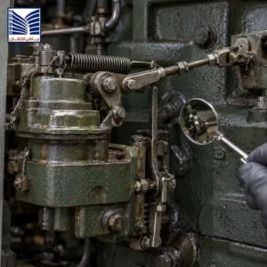
When Should Engineering Support Be Requested?
Request engineering support when multiple generators operate incorrectly, instability continues after basic verification, protection trips occur, commissioning issues remain unresolved, or system modifications are planned. Specialist review is also appropriate when the original controller files, setting records, CT/PT drawings, governor or AVR documentation, or commissioning reports are incomplete.
A structured assessment can separate the mechanical, governor, AVR, measurement, controller, communication, and protection domains. For systems involving protection relay systems, the review should include trip logic, setting coordination, event records, and the relationship between protection operation and load-sharing behavior.
Frequently Asked Questions
What causes generator load sharing problems?
Generator load sharing problems can be caused by governor or AVR mismatch, incorrect droop or voltage-reference settings, CT/PT polarity or scaling errors, controller configuration faults, communication loss, actuator or excitation limits, breaker feedback problems, or mechanical and electrical changes in the system. Begin by separating kW from kVAR behavior and compare operating data, feedback signals, controller alarms, and protection records before changing parameters.
Why do generators fail to share kW equally?
Generators may fail to share kW equally because their governors use different modes, droop values, gains, limits, or response times. An actuator, fuel system, speed sensor, or load-sharing signal can also be limiting one unit. Measurement errors may create a false imbalance. Confirm the intended proportional-sharing strategy, then compare frequency, speed reference, governor output, actuator response, and independent kW measurements during a controlled load change.
Why does kVAR sharing become unstable?
kVAR sharing can become unstable when AVR or excitation responses are mismatched, voltage references differ, reactive-current compensation is incorrect, or CT/PT phase, polarity, ratio, or scaling is wrong. Generator and transformer impedance can also affect reactive-current distribution. Check the measured voltage and reactive current, AVR mode, excitation output, limiter activity, and feedback wiring. Avoid adjusting voltage droop or gain until the sensing and system configuration are verified.
What causes generator hunting during parallel operation?
Generator hunting may result from excessive governor or AVR gain, slow actuator or excitation response, inconsistent droop or deadbands, noisy feedback, communication delay, competing control references, or a mechanical or electrical limitation. First determine whether frequency/kW or voltage/kVAR is oscillating, then review signals and timestamps across the units. Use controlled tests and change one authorized variable at a time; random adjustments can shift instability between control loops.
How do AVR and governor systems affect load sharing?
The governor and prime mover primarily influence frequency and active-power contribution, so their response affects kW sharing. The AVR and excitation system primarily influence terminal voltage and reactive-power contribution, so their response affects kVAR sharing. The loops interact through the common electrical system and controller logic. Incorrect feedback or communication can make either loop appear faulty, which is why kW, kVAR, frequency, voltage, references, and alarms should be reviewed together.
What should be checked before adjusting load sharing settings?
Before adjusting settings, record the existing parameters, controller mode, firmware, generator operating data, breaker status, frequency, voltage, kW, kVAR, governor and AVR signals, CT/PT feedback, alarms, protection status, and communication health. Verify wiring, ratios, polarity, scaling, and the intended sharing philosophy. Follow OEM documentation and the approved commissioning procedure. Define one test variable, expected response, rollback value, and acceptance condition before making a change.
Request Generator Synchronization and Load-Sharing Support
Request generator synchronization, load-sharing diagnostics, testing, or commissioning support when kW or kVAR drift, hunting, controller alarms, protection trips, or unresolved commissioning issues affect parallel operation. A technical review can help identify the affected control loop, validate measurements, preserve setting records, and coordinate governor, AVR, controller, communication, and protection checks. Use the contact technical support page.

