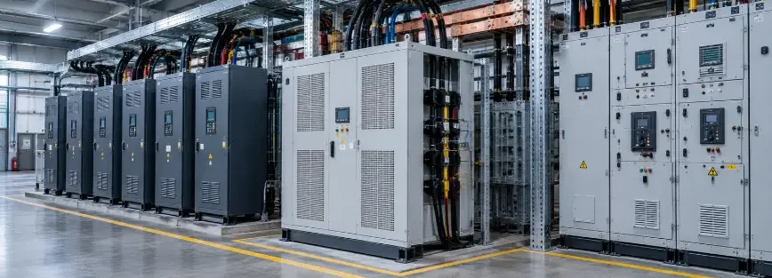
A harmonic filter in power system installations plays a central role in keeping a plant running smoothly, free from rising electrical losses, overheating risks, and unstable equipment performance.
It reduces the unwanted electrical harmonics created by non-linear loads such as variable frequency drives, converters, UPS systems, and industrial power electronics. In Saudi industrial facilities, this distortion can affect equipment performance, increase electrical losses, create overheating risks, and reduce overall power quality, putting reliability and critical electrical assets at risk.
But the right solution is never one-size-fits-all. It depends on load characteristics, network design, operating conditions, and future expansion requirements, so harmonic sources should be evaluated and system conditions measured before any mitigation approach is selected
What Is a Harmonic Filter in Power System?
A harmonic filter in power system is an electrical device designed to reduce harmonic currents and improve power quality by limiting unwanted frequency components generated by non-linear electrical loads. Depending on its type, it either provides a low-impedance path that diverts harmonic currents away from the network or injects opposing currents to cancel them.
These unwanted components are electrical harmonics: voltage or current distortions that occur when waveforms deviate from the ideal sinusoidal shape. They are usually produced by power electronic equipment in modern industrial facilities, such as variable frequency drives, UPS systems, battery chargers, rectifiers, and converters, and can lead to equipment failures, unexpected trips, and reduced system efficiency.
How Harmonic Filters Work in Industrial Electrical Systems
A harmonic filter reduces harmonic distortion either by diverting harmonic currents into a lower-impedance path or by generating compensating currents that cancel them out. This helps prevent excessive harmonic currents from flowing through transformers, cables, and sensitive equipment.
Non-linear loads such as variable frequency drives (VFDs), rectifiers, and UPS systems draw current in pulses rather than as a smooth sinusoidal waveform. This creates harmonic currents at whole-number multiples of the fundamental frequency, such as the 5th and 7th harmonics. If left uncontrolled, these currents flow through the network impedance and can distort the voltage seen by other connected equipment.
A filter addresses this problem near the harmonic source through one of two main approaches:
- Diversion: Harmonic current follows the lower-impedance path. A tuned filter’s capacitor-and-inductor branch is designed to present very low impedance at the targeted harmonic frequency, so more of that harmonic current flows through the filter rather than upstream into the supply network.
- Cancellation: The filter measures the load current, identifies its harmonic content, and uses power electronics to inject a compensating current with the appropriate magnitude and phase. This counteracts the harmonic current, while continuous measurement allows the correction to respond as the load changes.
Filters are often installed close to major harmonic-producing loads, although the optimum connection point depends on the system configuration and harmonic sources, as covered in the installation section below.
Types of Harmonic Filters: Passive, Active, and Hybrid
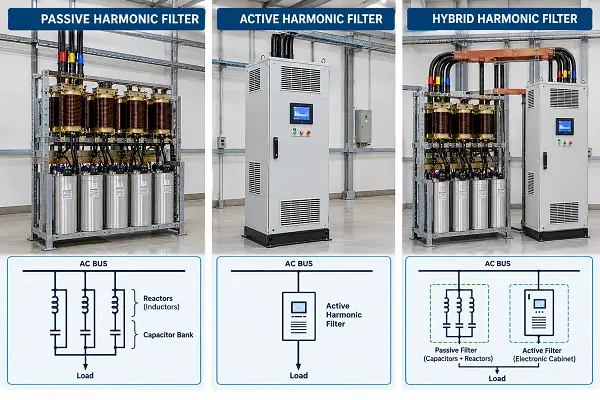
Harmonic filters fall into three main categories: passive, active, and hybrid. Each approach suits different load conditions, and the appropriate choice depends on the harmonic orders present, how much the load varies, the required level of mitigation, and how the electrical network may develop over time.
Passive harmonic filters use capacitors, inductors, and, in some designs, resistors to create a low-impedance path for targeted harmonic frequencies. They are commonly designed to address specific harmonic orders, such as the 5th and 7th harmonics often associated with six-pulse drives. Because their characteristics are largely fixed by the filter design, changes in load conditions can affect their performance.
Passive filters can also interact with the electrical network and create resonance risks, particularly in systems with capacitor banks. Existing network conditions, harmonic measurements, and planned system expansion should therefore be assessed before selecting and tuning a passive filter.
Active harmonic filters use power electronic technology to monitor load current and inject a compensating current that reduces harmonic content dynamically. They can provide compensation across a broad range of harmonic orders and respond to changing load conditions, making them suitable for industrial environments where harmonic levels vary significantly during operation. Each active filter has a rated compensation current, so its capacity should be matched to the harmonic current that needs to be mitigated.
Hybrid harmonic solutions combine passive and active filtering methods. A passive stage can address dominant harmonic components, while an active stage provides dynamic compensation for remaining or changing harmonics. This approach can be considered when a facility requires targeted harmonic reduction together with greater adaptability to changing loads, while balancing the required active-filter capacity and overall system design.
Passive vs Active vs Hybrid Harmonic Filters: Quick Comparison
| Criteria | Passive | Active | Hybrid |
|---|---|---|---|
| Principle | Diverts targeted harmonic currents through a low-impedance path | Injects compensating current to reduce harmonics dynamically | Combines passive filtering with active compensation |
| Best suited for | Stable, predictable harmonic conditions | Variable or complex harmonic conditions | Mixed or changing harmonic requirements |
| Typical applications | Fixed-load drive applications and systems with known harmonic orders | Variable-speed drives, welding equipment, and other fluctuating industrial loads | Large facilities with mixed loads and varying harmonic conditions |
| Main consideration | Resonance and tuning requirements | Rated compensation current and capacity | Greater design and coordination complexity |
How to Select and Size the Right Harmonic Filter
Selecting an electrical harmonic filter requires a structured engineering approach. Installing filtering equipment without understanding the electrical system may not address the actual cause of harmonic problems, and an undersized or wrongly tuned filter can make things worse.
- Identify harmonic sources. List the drives, converters, UPS systems, and large electronic loads, including planned additions.
- Review system conditions. Check transformer capacity, short-circuit levels, distribution layout, protection, and LV or MV level. The load’s size relative to the network’s short-circuit strength affects voltage distortion. Note any capacitor banks, as they influence filter type and resonance risk.
- Measure harmonic levels. Voltage and current measurements under real operating conditions provide the data sizing depends on. See our Power Quality Analysis Services and the verification section below.
- Understand load characteristics. Industrial loads are rarely constant, so consider normal operation, peak demand, motor starting, and future expansion.
- Size to a target. Define the harmonic limits at the point of common coupling, then size against the measured harmonic current: a passive filter by its tuned orders and reactive power rating, an active filter by the compensation current it must supply.
- Select the approach. Stable loads usually suit passive filters, varying loads suit active filters, and mixed conditions may call for a hybrid. Weigh compatibility, maintenance, and long-term needs.
Where Should a Harmonic Filter Be Installed?
The best location for a harmonic filter in power system is as close as practical to the harmonic-producing loads, but the right point depends on the number of loads, capacitor bank locations, and the harmonic limits that must be met.
There are three common installation levels:
- At the individual load: A filter installed at a large drive reduces harmonic current close to the source and limits its flow into the upstream network.
- At a motor control center or distribution board: One filter can serve a group of non-linear loads connected to the same distribution point.
- At the main bus or point of common coupling (PCC): A filter at the incoming supply can address harmonic performance at the utility connection, although harmonic currents may still circulate through internal cables and transformers before reaching the filter.
Before selecting the installation point, consider:
- Capacitor banks: Review the filter location together with existing capacitor banks to avoid resonance and other network interactions.
- Voltage level: LV and MV systems require different filter designs and connection arrangements.
- Current measurement: Active filter sensors must be positioned to accurately measure the harmonic currents being compensated.
- Site conditions and expansion: Space, ventilation, access, and future loads can affect the installation location and long-term suitability.
Harmonic Filters and Capacitor Banks: Resonance Considerations
A capacitor bank can amplify harmonics instead of absorbing them. Power factor correction capacitors can form a resonant circuit with the network’s inductance, and if the resonant frequency falls near a harmonic produced by the plant, such as the 5th or 7th, harmonic currents and voltages can increase, leading to capacitor failures, blown fuses, and nuisance tripping.
To reduce this risk, measure the harmonic spectrum before adding or modifying a capacitor bank, and consider detuning reactors or a properly designed filter. Passive filters should also be designed together with existing capacitor banks because they introduce their own resonance below the tuned frequency.
How to Verify Harmonic Filter Performance
A filter is only proven by measurement: compare harmonic levels before and after installation, at the same points and under comparable load conditions.
- Record a baseline before installation: Power quality analysis shows how severe the problem is by measuring:
- Total harmonic distortion (THD)
- Individual harmonic levels
- Voltage distortion
- Current distortion
- Load behavior during different operating conditions
- Measure again after commissioning: Repeat the same measurements at the same points, during normal and peak load. The results should demonstrate the required reduction in harmonic distortion and confirm that the applicable limits are met at the point of common coupling.
- Confirm the harmonic orders were reduced: Check the individual harmonics the filter was designed for, such as the 5th and 7th, and check for any unexpected amplification at other frequencies, particularly where capacitor banks are present.
- Check whether the symptoms are gone: Motor overheating, frequent trips, and capacitor failures can also come from other electrical problems, so use the measurements, not the symptoms alone, to confirm that harmonics were the cause.
- Keep monitoring after commissioning: A filter sized for today’s load may not suit the plant in two years. Added equipment, production expansion, changing load patterns, and aging components all shift the harmonic profile, so periodic measurements at the same points show whether the filter is still performing as intended, before the change turns into repeated trips or overheating.
Why Choose RETQAN for Your Harmonic Filter Needs
Choosing the right harmonic filter in power system starts with understanding both the drives causing the distortion and the electrical network affected by it. RETQAN combines experience in industrial drives, automation systems, and electrical power systems to assess harmonic sources and identify suitable mitigation approaches.
From assessing harmonic sources to selecting the right electrical harmonic filter and supporting LV/MV drive and switchgear upgrades, RETQAN provides engineering support based on the facility’s electrical system and operating conditions.
FAQ
Does a harmonic filter save energy or reduce electricity bills?
Sometimes, but energy saving is not its main purpose. Reducing harmonic currents can lower losses in cables and transformers and reduce total current demand. However, the effect on electricity bills depends on the facility and its tariff. The main benefits are improved equipment reliability and compliance with applicable utility limits. Filters also have small losses of their own.
How long does a harmonic filter last, and does it need replacement?
Service life depends on the filter type, design, operating temperature, and maintenance. Capacitors and cooling fans are among the components most likely to require servicing or replacement over time. After major plant expansions, the filter should also be re-evaluated to confirm that it remains suitable for the changed load conditions.
What happens if I don’t install a harmonic filter?
Not every facility needs one, so harmonic levels should be measured first. If distortion is excessive, harmonic currents can increase heating and losses in transformers, cables, and motors and may contribute to nuisance tripping, capacitor failures, and utility-limit violations. Because these symptoms can have other causes, measurements should confirm the harmonic problem before selecting a filter.