

A PLC SCADA SAT checklist helps commissioning teams verify that an installed automation system behaves according to approved project requirements before acceptance or handover. A successful Factory Acceptance Test (FAT) does not automatically prove that field wiring, installed devices, site networks, third-party interfaces, and integrated control sequences work correctly at the actual facility. Site Acceptance Testing (SAT) addresses these site-dependent conditions and documents the results. A useful SAT report should identify the approved test scope, expected and actual results, supporting evidence, unresolved defects, retest outcomes, and final configuration status. Acceptance criteria must come from the approved project specifications, contract, and applicable test procedures.
Quick Answer: What Should a PLC/SCADA SAT Report Prove?
A PLC/SCADA Site Acceptance Test report should demonstrate which installed-system functions were tested, which approved requirements were used, whether the expected results were achieved, and what evidence supports each recorded outcome. It should also identify failed, deferred, excluded, and incomplete tests rather than presenting the entire system as accepted when outstanding items remain.
A practical SAT report should address the following areas where they are included in the approved scope:
- Approved requirements, test procedures, and acceptance criteria.
- Site readiness, test preconditions, and authorization.
- Field I/O, installed devices, and signal mapping.
- PLC, SCADA, and third-party communications.
- Control sequences, interlocks, and integrated functions.
- Alarms, HMI screens, trends, and historian tags where applicable.
- Defects, corrective actions, retests, and outstanding items.
- Software baselines, as-built documentation, and handover records.
The exact acceptance criteria and test coverage depend on the contract, approved project specifications, system architecture, and applicable commissioning procedures. A generic checklist supports planning but does not guarantee acceptance or replace the approved SAT procedure.
What Is Site Acceptance Testing for PLC and SCADA Systems?
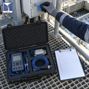
Site Acceptance Testing is the process of verifying an installed system against the applicable approved requirements within the defined site-test scope. For industrial automation, SAT may cover field signal integration, control-system communications, operator interfaces, alarms, control sequences, and interfaces with other equipment or systems.
Unlike factory testing, SAT considers conditions associated with the actual installation. Depending on the project, these may include field wiring, installed instruments, communication paths, device feedback, third-party interfaces, and interactions between the PLC, SCADA, HMI, and other control systems.
Typical SAT activities may include:
- Confirming that installed signals correspond to the intended control-system points.
- Checking relevant field-device status and feedback.
- Verifying communication and data exchange across included interfaces.
- Testing defined control sequences against approved functional descriptions.
- Checking alarm generation and operator-interface indications.
- Verifying applicable trends, historian tags, and displayed engineering units.
- Recording actual results and discrepancies against approved requirements.
SAT is not simply routine maintenance or general troubleshooting. It is a structured verification activity with an agreed scope, defined acceptance criteria, and traceable test evidence. Its purpose and extent should be established by the project documentation.
FAT vs. SAT: What Is the Difference?
Factory Acceptance Testing and Site Acceptance Testing serve related but distinct purposes. FAT typically verifies agreed system functions in a factory or other designated test environment before shipment or delivery. SAT verifies the installed system and its site-dependent integration within the approved scope.
| Engineering Aspect | Factory Acceptance Testing (FAT) | Site Acceptance Testing (SAT) |
|---|---|---|
| Main setting | Factory or agreed test environment | Actual installation or approved site-test environment |
| Primary focus | Agreed system functions before shipment or delivery | Installed-system behavior and site integration |
| Typical evidence | Factory test records and approved FAT results | Site test records, field observations, and integration results |
| Field wiring and devices | May be simulated or represented in the factory test | Verified to the extent defined in the SAT scope |
| Site communication paths | May be simulated or unavailable | Checked against the installed architecture where included |
| Integrated plant interfaces | Limited to the agreed factory-test scope | Verified according to the approved site integration scope |
| Handover relevance | Provides pre-shipment test evidence | Supports site acceptance and handover decisions |
A successful FAT is valuable evidence, but it cannot automatically establish that every installed component and site-dependent function has been verified. Equally, SAT does not necessarily need to repeat every FAT test. The test plan should address site-specific risks, outstanding FAT items, contractual obligations, and the interfaces that require verification at the installation.
Why Can a System Pass FAT but Fail During Site Integration?
A control system can perform as expected in a factory test environment but behave differently after installation. This may happen because the factory environment cannot reproduce every field device, wiring condition, communication path, or operational dependency present at the site.
Potential causes include:
- Incorrect or incomplete field wiring: an installed signal may not reach the intended control-system input or output.
- I/O addressing discrepancies: a signal may be mapped to an incorrect or unexpected point.
- Field-device problems: an instrument, actuator, or feedback device may not provide the expected response.
- Signal scaling errors: values or engineering units may not match the approved configuration.
- Communication configuration issues: addressing, data mapping, or other settings may differ from the intended site architecture.
- Third-party interface differences: an external system may exchange data differently from the assumptions used during factory testing.
- Configuration changes: the installed software or configuration may differ from the tested baseline.
- Integrated sequence issues: individual functions may work separately while a combined sequence does not behave as specified.
- Alarm and HMI discrepancies: tag associations, alarm descriptions, or displayed statuses may not match the approved requirements.
- Unavailable site dependencies: certain operating conditions or interfaces may not have been accessible during FAT.
These are examples of possible causes, not findings about a specific project. A structured SAT helps identify discrepancies by comparing the actual site response with the approved functional requirements.
What Should Be Checked Before Starting a PLC/SCADA SAT?
1. Approved Documents and Test Scope
Before testing begins, the commissioning team should establish which documents define the expected behavior and which functions are included in the SAT.
- Approved functional description and control philosophy.
- I/O list and signal descriptions.
- Cause-and-effect matrix, where applicable.
- Approved SAT procedures and acceptance criteria.
- Network and interface architecture.
- Alarm and HMI requirements.
- FAT report and outstanding punch-list items.
- Relevant electrical, instrumentation, and control drawings.
- Project specifications and applicable contractual requirements.
- Software and configuration revision records.
The applicable revisions should be identifiable and consistent with the configuration to be tested. Any document conflict that affects the expected response should be resolved through the approved engineering process before the relevant test proceeds.
2. Site Readiness and Preconditions
Site readiness establishes whether the required conditions for a valid test are available. The checks depend on the equipment, installation, and approved test scope.
- Confirm installation readiness for the functions under test.
- Verify the availability of required field devices and interfaces.
- Confirm the approved test environment and test boundaries.
- Check the availability of communication and power where relevant.
- Confirm required permits, authorizations, and safety controls.
- Coordinate test activities with operations and other contractors.
- Review applicable isolation arrangements and operational constraints.
- Confirm that required personnel and test records are available.
There is no single site-readiness sequence that applies to every project. The responsible team should follow the approved commissioning plan and the site’s applicable safety and authorization requirements.
3. Software and Configuration Baseline
Test results are meaningful only when the configuration being tested is identifiable. The SAT records should therefore capture the relevant PLC, SCADA, HMI, and interface revisions as required by the project.
Review the following where applicable:
- Approved software version and configuration revision.
- Relevant tag and I/O mappings.
- Configuration backups and recovery arrangements.
- Approved change records.
- Modifications introduced after FAT.
- Outstanding configuration issues.
The project may use different configuration-management methods depending on its system design. The objective is to identify the as-tested configuration and maintain traceability between approved changes, test results, and final handover records.
PLC SCADA SAT Checklist: Main Functional Test Areas
The main practical purpose of a PLC SCADA SAT checklist is to connect each relevant requirement to a test, an expected result, an observed result, and evidence. The following areas should be considered according to the approved scope.
1. Field I/O and Signal Verification
Field I/O verification checks whether installed signals correspond to the intended control-system points and whether the observed behavior matches the approved requirements.
- Confirm signal identity and tag mapping.
- Verify input or output direction.
- Check expected normal and abnormal states where applicable.
- Review signal scaling and engineering units where relevant.
- Verify required device feedback.
- Check applicable status and fault indications.
- Record expected and actual results.
A simulated signal test is not automatically proof that the complete field installation is correct. Where the approved scope requires it, installed wiring, devices, and associated interfaces must be verified using the appropriate authorized procedure. Do not manipulate live process signals outside approved test controls.
2. Control Sequences and Interlocks
Control-sequence verification checks whether the installed control system follows the approved functional description. The test should cover the applicable initiating conditions, required sequence, interlock responses, and recovery behavior.
- Confirm the specified preconditions.
- Identify the initiating condition.
- Verify the expected sequence of operations.
- Check interlock and permissive responses.
- Verify relevant feedback confirmation.
- Check reset or recovery behavior where specified.
- Confirm expected alarms and status indications.
- Document any deviation from the approved requirements.
Actual logic, thresholds, timings, and acceptance criteria must come from approved project documents. A generic checklist must not be used to invent control behavior or authorize bypassing an interlock.
3. PLC, SCADA, and Third-Party Communications
Communication testing should reflect the installed system architecture. It verifies that the relevant interfaces exchange the expected information and present the correct status within the approved scope.
- Identify the communication paths included in the test.
- Confirm device and interface identification.
- Verify relevant data exchange and tag mapping.
- Check status and data-quality indications where applicable.
- Verify communication-loss behavior where specified.
- Check recovery behavior where required by the design.
- Review interfaces to relevant third-party systems.
Do not assume that every project uses the same communication protocol, network topology, or redundancy arrangement. The approved architecture and applicable equipment documentation define what must be verified.
4. Alarms and Alarm Routing
Alarm testing determines whether the relevant conditions produce the intended operator notifications and indications. Where included in the SAT scope, verification may cover:
- Required alarm generation.
- Correct alarm description and tag association.
- Priority and classification where specified.
- Operator visibility and presentation.
- Alarm routing or notification interfaces where applicable.
- Acknowledgment behavior where required.
- Alarm clearing and restoration behavior according to the approved design.
The SAT report should identify the alarms tested and record any exclusions. It should not imply that all alarms have been verified if the actual test covered only a defined subset.
5. HMI Screens, Trends, and Historian Tags
Human-machine interface testing checks whether the operator sees the information required by the approved design. If trends or historian functions are included, their relevant configuration and recorded data should also be reviewed.
- Verify tag-to-display mapping.
- Check displayed status and engineering units.
- Verify relevant operator commands and feedback.
- Review alarm presentation.
- Check trend configuration where applicable.
- Verify historian tag mapping and recorded values where included.
- Check timestamps and data continuity where required.
- Review operator navigation and access to relevant information.
Not every installation includes a historian, advanced trending, or the same HMI functions. The SAT scope should reflect the actual system configuration and approved requirements.
6. Integrated Functional Tests
Individual components may perform correctly when tested separately but still fail to deliver the required end-to-end function. Integrated testing checks the interactions between relevant components and system boundaries.
Generic examples include:
- A field condition being reflected in the PLC.
- The expected status appearing on the HMI.
- A defined control response being executed.
- An associated alarm being generated.
- A connected system receiving the expected signal.
- Relevant feedback or data being recorded.
These examples illustrate the concept of integration testing, not a universal test sequence. Actual test cases must follow the approved functional requirements, test boundaries, and applicable site controls.
7. Fault Handling and Recovery
Where required by the approved design, SAT may include verification of how the system responds to a defined fault condition and whether the expected recovery behavior occurs.
- Communication interruption.
- Loss of an expected signal.
- Device fault indication.
- Recovery after a defined fault condition.
- Alarm behavior during and after the condition.
- Restoration of the expected operating state.
Fault tests must be planned and authorized. Do not introduce uncontrolled faults into an operating process or assume a recovery sequence that is not documented in the approved design.
SAT Functional Test Coverage Table
| Test Area | What to Verify | Expected Evidence | Important Limitation |
|---|---|---|---|
| Field I/O | Signal identity, mapping, and expected response | Recorded input/output observations and test results | Simulation does not automatically prove the complete field installation |
| Control sequences | Approved sequence, interlocks, and feedback | Test case and actual response record | Use the approved functional description |
| Communications | Relevant data exchange, status, and interface behavior | Communication test records and observations | Scope depends on the installed architecture |
| Alarms | Generation, description, presentation, and applicable acknowledgment | Alarm test results and relevant evidence | Report untested alarms as exclusions or outstanding items |
| HMI and trends | Tag mapping, displayed values, and relevant recorded data | Observed screen values and applicable records | Only applicable configured functions should be claimed as tested |
| Fault recovery | Specified response and restoration behavior | Approved test results and recovery evidence | Tests require authorized procedures and safe conditions |
What Should a SCADA Commissioning Report Include?
A useful SCADA commissioning report provides traceable evidence of the tests actually performed. It should allow an owner engineer, EPC contractor, or QA/QC reviewer to understand the test scope, applicable requirements, observed outcomes, and unresolved issues without relying on assumptions.
| Report Element | What It Should Record |
|---|---|
| Project and system identification | Relevant project, system, and test references |
| Scope and exclusions | Functions included and excluded from the SAT |
| Reference documents | Applicable approved specifications and procedures |
| Test prerequisites | Preconditions and readiness status |
| Test case identification | Unique test ID and function under test |
| Expected result | Approved acceptance requirement |
| Actual result | Observed outcome |
| Evidence | Relevant logs, screenshots, records, or witnessed observations |
| Pass/fail status | Recorded result against the approved criterion |
| Defect reference | Identified discrepancy or punch-list item |
| Corrective action | Approved action taken, where applicable |
| Retest result | Outcome of the repeated test, if performed |
| Outstanding items | Unresolved defects, exclusions, and limitations |
| Configuration status | Relevant as-tested revision information |
| Sign-off | Required witness, reviewer, and approval records |
The report should distinguish clearly between completed tests, failed tests, deferred tests, and tests that were not applicable. A screenshot or general statement that a system is operational is not sufficient evidence for every function in a defined test scope.
How Should SAT Defects and Retesting Be Managed?
Defect management provides a controlled way to record discrepancies, assign corrective actions, and establish whether the affected functions have been retested. The process should follow the project’s agreed defect classification, responsibilities, and acceptance requirements.
For each discrepancy, record:
- The relevant SAT test case and approved requirement.
- The expected behavior and the actual observed behavior.
- A clear description of the discrepancy.
- The defect or punch-list reference.
- The responsible party, according to the agreed project process.
- The approved corrective action, where applicable.
- Whether a configuration or logic change requires formal approval.
- The retest result and supporting evidence.
- Any remaining limitation or outstanding action.
Defect severity and the implications for acceptance must follow the project’s agreed classification and contractual requirements. There is no universal rule that every outstanding item can be accepted or that every defect automatically prevents acceptance. The responsible project authorities must make that determination using the approved criteria.
What Should Be Completed Before SAT Handover?
Handover should include the records required by the contract, approved project procedures, and the owner or EPC contractor. The documentation should accurately represent the configuration tested and the status of the remaining activities.
Depending on the project scope, the handover package may include:
- Completed SAT report and applicable test procedures.
- Test evidence and referenced attachments.
- Updated test-case status and completion records.
- Defect and punch-list register.
- Approved change records.
- Applicable as-built drawings.
- Final I/O and tag documentation.
- Network and interface records.
- Software and configuration baseline information.
- Relevant backup and recovery records.
- Outstanding limitations, exclusions, and deferred tests.
- Training or operating documentation where included in the scope.
- Required witness, review, and sign-off records.
The final handover package must reflect the actual contractual scope and the records required by the responsible parties. It should not imply that deferred or excluded activities were completed.
Common Mistakes in PLC/SCADA SAT
Common SAT weaknesses include:
- Treating FAT completion as proof of site readiness: factory testing does not automatically verify installed wiring, field devices, and site interfaces.
- Repeating factory tests without addressing site-specific risks: this may leave the most important integration questions unanswered.
- Testing without approved acceptance criteria: the team may not have a reliable basis for deciding whether the result passes.
- Checking individual signals but overlooking integrated functions: separate component tests may not prove end-to-end behavior.
- Ignoring third-party communication paths: a required interface may remain unverified.
- Failing to verify alarm and HMI mapping: the operator may see incorrect or incomplete information.
- Recording only pass/fail: the report may lack evidence needed for independent review.
- Leaving failed tests without a resolution path: the status of unresolved issues becomes unclear.
- Ignoring configuration changes: test results may not correspond to the final installed configuration.
- Relying on a screenshot for every function: one image cannot necessarily prove the full sequence, field response, or communication behavior.
- Failing to distinguish test statuses: completed, failed, deferred, and excluded tests may be incorrectly presented as equivalent.
- Closing the report without documenting limitations: the receiving team may misunderstand what remains unverified.
These weaknesses can be reduced by defining the SAT scope early, maintaining document and configuration control, recording expected and actual results, and ensuring that unresolved defects remain visible until their status is formally addressed.
How PLC/SCADA Commissioning Support Can Help
Appropriate engineering support may help project teams review SAT scope, relate test cases to approved functional requirements, examine PLC/SCADA integration requirements, document discrepancies, and organize the evidence needed for handover. The actual service scope and responsibilities should be confirmed before the work is agreed.
For projects involving SCADA and HMI systems, the review may focus on operator interfaces, alarm presentation, communication with connected systems, and the relevant monitoring functions included in the approved requirements.
Where PLC logic and field signals are central to the SAT, PLC systems and solutions provide relevant context for reviewing control sequences, I/O mapping, and functional verification. If the project includes distributed control system interfaces, distributed control systems may also be relevant to the integration scope.
Before engaging engineering support, clarify the required deliverables, system boundaries, test responsibilities, documentation, acceptance criteria, and exclusions. A service enquiry should describe the actual installation and the required verification activities rather than assume that every test or service is automatically available.
Frequently Asked Questions About PLC/SCADA SAT
1. What Is a PLC/SCADA Site Acceptance Test?
A PLC/SCADA Site Acceptance Test verifies the installed automation system against applicable approved requirements within the defined SAT scope. It may include field I/O, communication paths, control sequences, alarms, HMI indications, and third-party interfaces. The test report records the expected and actual results, supporting evidence, defects, and retests. The exact coverage depends on the project specifications, installed architecture, and approved test procedures.
2. What Is the Difference Between FAT and SAT?
FAT generally verifies agreed system functions in a factory or designated test environment before delivery. SAT focuses on the installed system and site-dependent integration, such as field wiring, installed devices, communication paths, and interfaces within the approved scope. SAT does not necessarily repeat every FAT test. Instead, the test plan should address site-specific risks, outstanding FAT items, contractual requirements, and the functions that need site verification.
3. Why Can a PLC or SCADA System Pass FAT but Fail at Site?
A system may pass FAT but encounter site issues because the factory environment cannot reproduce every installed condition. Potential causes include incorrect field wiring, I/O mapping discrepancies, unexpected device feedback, communication configuration differences, third-party interface issues, or changes to the installed software baseline. These are possible causes, not automatic indicators of poor factory testing. SAT helps identify differences by comparing actual site behavior with approved requirements.
4. What Should a PLC SCADA SAT Checklist Include?
A PLC SCADA SAT checklist should address approved requirements, test preconditions, field I/O, communications, control sequences, alarms, HMI indications, and other functions included in the project scope. It should also identify expected results, actual observations, evidence, defects, and retests. The final checklist must be adapted to the installed architecture and approved acceptance criteria rather than applied as an identical universal procedure to every project.
5. What Should a SCADA Commissioning Report Contain?
A SCADA commissioning report should identify the system, test scope, reference documents, test cases, preconditions, expected results, actual results, and supporting evidence. It should record pass/fail status, defect references, corrective actions, retest outcomes, configuration information, and required sign-offs. The report should also distinguish completed tests from failed, deferred, excluded, or inapplicable activities so that reviewers can understand what was actually verified.
6. Should Field I/O and Third-Party Interfaces Be Tested During SAT?
Field I/O and third-party interfaces should be tested when they fall within the approved SAT scope and are required by the project’s acceptance criteria. Field checks may verify signal identity, mapping, device feedback, and expected states. Interface tests may verify relevant data exchange and status behavior. Simulation alone does not necessarily prove the complete field installation, and the actual test method must follow approved procedures and site safety controls.
7. How Should Failed SAT Tests and Outstanding Defects Be Documented?
Each failed test should be linked to its test case and source requirement, with a clear comparison of expected and actual behavior. The record should identify the discrepancy, relevant defect reference, corrective action, and retest result where applicable. Outstanding items must remain visible in the report or defect register. Severity, responsibilities, and acceptance implications should follow the project’s agreed process rather than an invented universal classification.
8. What Documents Should Be Delivered After PLC/SCADA SAT?
Depending on the project, handover records may include the completed SAT report, test evidence, updated test status, defect register, approved change records, as-built drawings, final I/O and tag documentation, interface records, software configuration baseline, relevant backups, and required sign-offs. The package should identify exclusions, deferred tests, and outstanding limitations. The contract and approved project procedures determine which records are mandatory for formal handover.

Request a PLC/SCADA Commissioning Scope Review
Industrial project teams preparing for site acceptance can request a technical discussion about their PLC/SCADA commissioning requirements, site integration scope, testing documentation, and handover deliverables. To make the discussion productive, prepare the relevant project specifications, functional descriptions, FAT report, outstanding punch-list items, system architecture, and current configuration records where available.
Use the contact page to discuss your PLC/SCADA commissioning requirements and clarify the required engineering review, testing responsibilities, documentation, and scope exclusions.
Conclusion
A useful PLC SCADA SAT checklist connects approved requirements to the actual behavior of the installed automation system. It should address site-dependent risks that may not have been fully represented during FAT, including field I/O, communications, integrated sequences, alarms, operator interfaces, and relevant third-party systems.
The SAT report should document what was tested, what passed or failed, what remains outstanding, and which evidence supports the recorded results. Clear defect management, configuration control, and accurate handover records help owner engineers, EPC contractors, commissioning leads, and QA/QC teams review the status of the system against the project’s acceptance requirements. The final acceptance decision remains subject to the contract, approved specifications, and designated project authorities.