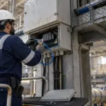

Switchgear failure modes are the ways electrical distribution equipment can malfunction, including insulation breakdown, overheating, contact deterioration, circuit breaker operating failures, and control circuit faults. Understanding these failure mechanisms helps industrial maintenance teams identify warning signs, select appropriate diagnostic tests, and assess risks to the wider electrical network. In Saudi industrial facilities, where electrical distribution equipment may operate under demanding loads and environmental conditions, a structured approach to switchgear troubleshooting and preventive maintenance can help reduce unexpected outages and identify developing defects before they escalate. Effective diagnosis requires more than identifying an alarm: engineers must correlate equipment condition, operating history, protection records, and test results before deciding on corrective action.
What Causes Switchgear Failure?
Switchgear controls, protects, and isolates electrical circuits. Depending on the installation, it may include circuit breakers, disconnectors, busbars, current and voltage transformers, protection relays, control circuits, auxiliary power supplies, and interlocking mechanisms.
Switchgear failure can result from a single defect or several contributing conditions. For example, a deteriorated connection may produce localized heating, which accelerates insulation ageing and eventually contributes to a more serious electrical fault.
The most common contributing factors include:
- Insulation deterioration: Ageing, contamination, moisture, electrical stress, and unsuitable operating conditions can weaken insulation between conductors or between energized components and earth.
- Overheating: Excessive current, poor contact pressure, loose connections, inadequate ventilation, or damaged conductors can produce abnormal temperature rise.
- Electrical connection defects: Loose, corroded, contaminated, or damaged connections may increase resistance and create localized hot spots.
- Mechanical wear: Springs, linkages, operating mechanisms, latches, and other moving parts can deteriorate or become obstructed.
- Contact erosion: Repeated switching and fault interruption can wear contacts, depending on the equipment design and operating duty.
- Environmental exposure: Dust, humidity, condensation, corrosive contaminants, and unsuitable enclosure conditions can affect insulation and mechanical operation.
- Control circuit faults: Damaged wiring, defective auxiliary contacts, failed coils, blown fuses, or unreliable auxiliary supplies can prevent correct breaker operation.
- Protection and configuration issues: Incorrect settings, unsuitable coordination, wiring errors, or logic problems may cause unwanted trips or prevent the intended trip command from operating correctly.
- Inadequate maintenance: Missed inspections, incomplete testing, unresolved defects, and poor maintenance records can allow developing problems to remain undetected.
It is important to distinguish the cause from the symptom. A temperature alarm, for example, indicates an abnormal condition that requires investigation; it does not by itself establish whether the underlying cause is excessive load, a defective connection, cooling problems, or another mechanism.
What Are the Main Switchgear Failure Modes?
The relevant failure modes depend on whether the equipment is low-voltage (LV) or medium-voltage (MV), its design, its operating duty, and the surrounding electrical system.
1. Insulation Failure
Insulation failure occurs when an insulating system can no longer withstand the electrical stress applied to it. It may result in phase-to-phase or phase-to-earth faults, depending on the location and characteristics of the defect.
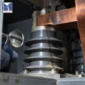
Potential contributors include contamination, moisture, thermal ageing, surface tracking, mechanical damage, and electrical stress. In medium-voltage equipment, partial discharge may provide an indication of localized insulation deterioration when the equipment design and selected measurement method make that assessment applicable.
Warning indicators may include abnormal discharge activity, insulation test results that change significantly from an established baseline, visible contamination, or a protection operation consistent with an insulation fault.
Engineering response: Review the fault history and environmental conditions, inspect the relevant equipment under an approved safe-work procedure, and select insulation or partial-discharge diagnostics appropriate to the equipment. A single measurement should not be treated as a complete diagnosis.
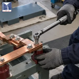
2. Busbar and Connection Overheating
Busbars distribute electrical power between incoming feeders, outgoing circuits, and other switchgear components. Excessive heating at a busbar joint, cable termination, or contact interface can indicate increased electrical resistance or excessive loading.
Possible causes include loose or deteriorated joints, oxidation, damaged contact surfaces, load imbalance, and inadequate thermal design for the actual operating conditions.
Infrared thermography may help identify abnormal temperature patterns during suitable operating conditions. However, temperature comparisons must account for load current, ambient conditions, measurement access, and the characteristics of the equipment.
Engineering response: Investigate the temperature pattern, loading history, and connection condition. Any intrusive inspection, tightening, or repair must follow approved isolation procedures and the manufacturer’s requirements.
3. Circuit Breaker Failure to Open or Close
A circuit breaker may fail to operate because of mechanical defects, a failed operating coil, control supply problems, damaged auxiliary contacts, wiring faults, or an interlock condition that prevents operation.
Failure to open when required can prevent the intended fault isolation. Failure to close can prevent restoration of a circuit or leave an essential load unavailable.
Warning signs include repeated unsuccessful operating commands, abnormal operating times, inconsistent position indications, or a breaker that does not reach its expected state.
Engineering response: Review the operating sequence, control circuit, auxiliary supply, interlocks, mechanical condition, and event records. Circuit breaker timing and functional tests may be appropriate when conducted using approved procedures and equipment-specific criteria.
4. Contact Deterioration
Switching duty and fault interruption can affect contact surfaces over time. Excessive contact wear or damage may increase resistance, affect interruption performance, or indicate that further inspection is needed.
The extent of deterioration cannot be determined reliably from operating hours alone. The number and severity of switching operations, fault history, equipment design, and maintenance records are also relevant.
Engineering response: Compare inspection and contact resistance findings with the manufacturer’s criteria and historical records. Determine whether maintenance, further testing, or replacement is appropriate for the actual equipment condition.
5. Mechanical Operating Mechanism Failure
Operating mechanisms convert a control command into breaker movement. Problems involving springs, linkages, latches, lubrication, or mechanical adjustment can affect the opening and closing sequence.
Possible indicators include inconsistent operating times, unusual mechanical noise, incomplete travel, or failure to achieve the required position.
Engineering response: Review the manufacturer’s inspection requirements and assess the mechanism using approved procedures. Do not attempt adjustments based solely on sound or visual symptoms.
6. Control Circuit and Auxiliary Supply Faults
Control circuits carry commands and status signals between local controls, protection relays, breaker mechanisms, and supervisory systems. Auxiliary supplies may power trip coils, close coils, relays, indication circuits, and other control components.
A loss of auxiliary power, wiring defect, failed fuse, or defective relay contact can interrupt the expected control sequence.
Engineering response: Examine the relevant control schematic, supply status, wiring records, terminal condition, and circuit test results. Confirm that the problem is not caused by an interlock or a legitimate protection condition before considering component replacement.
7. Protection Relay or Trip Circuit Problems
Protection relays detect abnormal electrical conditions and issue trip commands according to their configured protection philosophy. A relay may operate incorrectly because of unsuitable settings, incorrect current-transformer or voltage-transformer inputs, configuration errors, wiring defects, or a failed output circuit.
The trip command and the physical opening of the breaker are separate stages. A relay event record may confirm that a trip was initiated, but it does not necessarily prove that the breaker successfully interrupted the current.
Engineering response: Compare relay event records with breaker status, trip circuit indications, fault records, and approved protection settings. Where relevant, review the system’s protection relay solutions in the context of the wider protection scheme.
8. Environmental and Auxiliary Component Failures
Heaters, fans, thermostats, position switches, indication lamps, and other auxiliary components can fail without immediately producing a major electrical fault. However, these defects may affect enclosure conditions, status visibility, or the correct operation of control and protection functions.
In facilities exposed to dust, humidity, condensation, or high ambient temperatures, enclosure condition and environmental control deserve particular attention.
Engineering response: Review auxiliary component alarms, inspection findings, environmental conditions, and maintenance history. Confirm the function and suitability of replacement components before returning the equipment to service.
What Happens When Switchgear Fails?
The consequences of a switchgear failure depend on its location, fault type, network topology, protection coordination, and available alternative supply paths.
Potential consequences include:
- Unplanned loss of power to one or more loads.
- Protective device operation and isolation of an affected circuit.
- Damage to switchgear or connected equipment.
- Interruption of production or facility services.
- Loss of redundancy where an alternative supply path is unavailable.
- Increased troubleshooting and restoration requirements.
- Electrical hazards to personnel if equipment condition or isolation is not properly managed.
A fault on a single outgoing feeder may remain limited to that circuit if the protection scheme operates as intended. A fault affecting a busbar or a critical upstream component may have a wider impact because several downstream circuits depend on the same distribution point.
For this reason, switchgear troubleshooting should consider the complete distribution arrangement rather than treating every fault as an isolated component problem.
Common Problems and Symptoms in Switchgear
The table below links common failure modes to possible causes and suitable diagnostic approaches. These are investigation guides, not definitive symptom-to-fault rules.
| Failure mode or problem | Possible causes | Observable warning signs | Potential consequences | Recommended diagnostic approach |
|---|---|---|---|---|
| Insulation deterioration | Ageing, contamination, moisture, electrical stress | Abnormal insulation test trends, discharge indications, visible contamination | Earth fault, phase fault, equipment damage | Review history and select suitable insulation diagnostics |
| Busbar or connection overheating | Loose joint, increased contact resistance, excessive load | Abnormal thermal pattern, discoloration where safely visible | Insulation damage, connection failure | Thermography under suitable conditions, followed by approved inspection |
| Breaker fails to open | Trip circuit fault, mechanism defect, failed coil | Trip command without expected position change | Fault may not be isolated as intended | Review trip circuit, event records, and breaker operation |
| Breaker fails to close | Close circuit defect, interlock, auxiliary supply issue | Failed closing sequence, unexpected status | Circuit remains unavailable | Review interlocks, control supply, wiring, and mechanism |
| High contact resistance | Worn, damaged, or contaminated contacts | Abnormal measurement compared with suitable baseline or criteria | Excessive heating, degraded contact performance | Contact resistance measurement and equipment-specific assessment |
| Auxiliary supply failure | Failed fuse, power supply defect, wiring issue | Loss of indication, control alarms, unavailable functions | Control or protection functions may be affected | Review auxiliary supply and control circuit records |
| Protection relay malfunction or misconfiguration | Incorrect settings, input wiring error, output circuit defect | Unexpected trip, missing trip, inconsistent event records | Incorrect or delayed fault isolation | Review settings, records, wiring, and approved test results |
| Environmental deterioration | Condensation, dust, corrosion, poor enclosure condition | Moisture, contamination, repeated auxiliary alarms | Insulation or mechanical problems | Environmental inspection and review of enclosure requirements |
A warning sign should trigger a proportionate investigation. It should not automatically trigger component replacement, and the absence of visible symptoms does not prove that the equipment is healthy.
Testing and Diagnostic Methods for Switchgear
No single diagnostic method identifies every switchgear failure. Engineers should choose tests based on the equipment design, suspected defect, available evidence, and applicable maintenance or commissioning requirements.
Visual Inspection
Visual inspection can identify accessible signs of contamination, corrosion, mechanical damage, overheating, moisture ingress, or missing components. It can also reveal discrepancies between the equipment’s physical condition and its documentation.
Inspection boundaries depend on the equipment design and safety controls. Covers and compartments must not be opened unless the work is authorized and carried out under the applicable site procedures.
Infrared Thermography
Infrared thermography helps identify temperature differences that may indicate abnormal heating at accessible connections or components.
Results are most useful when interpreted alongside load current, ambient temperature, operating conditions, and comparable historical measurements. A thermal image alone may not identify the root cause of a hot spot.
Insulation Resistance Testing
Insulation resistance testing can help assess the condition of certain insulation systems when the method is appropriate for the equipment.
Test voltage, preparation, isolation, connected electronics, environmental conditions, and acceptance criteria must follow the applicable equipment documentation and approved procedure. Test results should not be compared indiscriminately across different equipment types or test conditions.
Contact Resistance Measurement
Contact resistance measurement can help investigate conductive paths through contacts and connections. It is useful when contact deterioration or connection resistance is suspected.
Interpretation should consider equipment design, measurement method, temperature, and manufacturer acceptance criteria. A single value without suitable reference information may be inconclusive.
Circuit Breaker Timing and Operating Tests
These tests assess selected aspects of breaker opening and closing performance, such as operating time and the relationship between poles where relevant.
The required measurements depend on breaker design and the maintenance objective. Results should be compared with the manufacturer’s criteria or approved project requirements rather than universal limits.
Protection Relay and Trip Circuit Verification
Protection testing helps confirm that the relevant inputs, logic, output contacts, trip circuits, and associated breaker responses perform as intended within the approved test scope.
Testing should use approved procedures, suitable equipment, and appropriate isolation arrangements. Relay records and breaker status should be reviewed together to distinguish a protection decision from the physical operation of the switching device.
Partial Discharge Assessment
Partial discharge assessment may help investigate insulation defects in equipment for which the method is suitable. Its value depends on insulation technology, sensor arrangement, background interference, operating conditions, and interpretation expertise.
It is not applicable in the same way to every LV or MV assembly, and a detected signal requires contextual assessment before drawing conclusions.
Alarm and Event Record Review
Protection relay event records, SCADA alarms, breaker status changes, and maintenance logs can help establish when a problem began and how the system responded.
These records are particularly valuable when faults are intermittent or occur under specific operating conditions. Time synchronization, event completeness, and correct status mapping should be considered before reconstructing the sequence.
Relevant equipment documentation and applicable standards provide the basis for selecting tests and interpreting results. For LV assemblies, the IEC 61439 series addresses assembly requirements and verification; for applicable metal-enclosed AC switchgear above 1 kV and up to 52 kV, IEC 62271-200 provides relevant requirements. The applicable edition, product type, and project specifications must be confirmed before testing or acceptance decisions are made.
Preventive Maintenance Strategies for Switchgear
Switchgear preventive maintenance aims to identify deterioration, verify essential functions, and correct defects before they lead to more serious operational problems. The appropriate strategy depends on equipment criticality, service conditions, manufacturer guidance, maintenance history, and the consequences of failure.
A practical maintenance program combines planned inspections with condition-based investigations when credible evidence indicates a developing problem.
Switchgear Maintenance Planning Checklist
| Maintenance activity | Purpose | Relevant evidence or records | Frequency considerations |
|---|---|---|---|
| Review operating history | Identify recurring trips and abnormal operating patterns | Fault logs, alarms, operator reports | Review according to the maintenance plan and after significant events |
| Inspect enclosure condition | Identify contamination, corrosion, moisture, or damage | Inspection checklist, photographs, defect records | Based on environment, enclosure design, and equipment criticality |
| Inspect mechanical components | Assess visible deterioration and operating mechanism condition | Inspection records, manufacturer instructions | According to equipment-specific maintenance requirements |
| Review electrical connections | Investigate suspected heating or connection deterioration | Thermal records, approved inspection findings, test results | Based on condition, operating duty, and approved procedures |
| Verify breaker operation | Assess selected opening, closing, and indication functions | Functional test results, timing records where applicable | Based on manufacturer guidance, switching duty, and maintenance strategy |
| Review protection and trip circuits | Identify wiring, setting, or functional discrepancies | Approved settings, test sheets, event records | After relevant changes, repairs, or according to the maintenance plan |
| Review auxiliary supplies | Confirm the condition of relevant control power and auxiliary functions | Supply checks, alarms, maintenance records | According to equipment criticality and identified defects |
| Close out corrective actions | Confirm that reported defects have been addressed | Work orders, test evidence, approval and handover records | After each corrective maintenance activity |
Maintenance intervals should not be selected from a generic checklist alone. Use the equipment manufacturer’s recommendations, applicable standards, service conditions, switching duty, equipment criticality, and approved site procedures.
Condition-Based Maintenance
Condition-based maintenance uses evidence about the actual condition of equipment to help prioritize maintenance activities. Depending on the switchgear design and available monitoring, evidence may include thermal trends, operating records, insulation diagnostics, breaker operation results, and repeated alarms.
A useful process is to:
- Establish a baseline using appropriate inspection and test records.
- Record abnormal conditions and changes from the baseline.
- Evaluate findings in the context of loading and operating conditions.
- Determine whether further testing or corrective work is justified.
- Record the investigation, approved action, and verification results.
- Update the maintenance plan when findings indicate that the existing approach needs review.
Condition-based maintenance does not eliminate the need for scheduled inspections or manufacturer-required activities. It helps teams make more informed decisions about where additional attention may be needed.
Integration with Protection Relays and SCADA Systems
Switchgear reliability depends partly on how equipment, protection, control, and monitoring functions work together. Protection relays detect specified abnormal electrical conditions and initiate actions according to the approved protection scheme. SCADA systems provide supervisory visibility through measurements, alarms, status indications, and event records.
These functions complement each other but are not interchangeable.
The Role of Protection Relays
Protection relays may detect overcurrent, earth faults, differential conditions, or other defined electrical abnormalities, depending on the protection design.
When a protection element operates, the relay may issue a trip command to the relevant circuit breaker. Engineers must verify the complete response rather than assuming that a recorded trip command proves successful fault clearance.
A useful investigation correlates:
- The original protection element or alarm.
- The relay’s recorded trip decision.
- Trip circuit status and available monitoring.
- Breaker auxiliary contact indications.
- Breaker operation records.
- Upstream and downstream protection events.
Where the fault history suggests a protection or coordination issue, an engineering review of the protection scheme may be appropriate.
The Role of SCADA Monitoring
SCADA monitoring can help operators recognize abnormal states, review alarm sequences, and compare equipment status with operating conditions. For example, a breaker position discrepancy or a repeated auxiliary supply alarm may provide an early indication that further investigation is necessary.
However, an alarm is only useful if the underlying signal, alarm configuration, communication path, and displayed status are correct. Missing or delayed information can complicate troubleshooting.
SCADA does not replace the required electrical protection functions. Protection design, trip logic, circuit breaker performance, and coordination must be assessed independently and as part of the complete system.
For industrial facilities reviewing their distribution equipment, the relevant LV/MV switchgear systems should be considered alongside the associated protection and monitoring arrangements.
Safety Precautions When Working with Switchgear
Switchgear may contain hazardous electrical energy even when some control functions appear inactive. Maintenance and testing must be planned around the actual equipment configuration and the hazards identified for the work.
Essential precautions include:
- Qualified and authorized personnel: Work must be carried out by personnel with the appropriate training, authorization, and task-specific competence.
- Risk assessment: Identify electrical, mechanical, stored-energy, arc-flash, and environmental hazards relevant to the equipment and task.
- Approved isolation: Apply the site’s authorized isolation and lockout/tagout process where required.
- Verification of the safe state: Confirm the de-energized condition using the approved procedure and suitable instruments before work that requires isolation.
- Stored energy management: Account for spring-charged mechanisms, capacitors, auxiliary supplies, and other stored-energy sources.
- Suitable test equipment: Confirm instrument ratings, condition, and suitability for the intended measurement.
- Personal protective equipment: Use the PPE specified by the risk assessment and site requirements.
- Controlled restoration: Complete inspections, close work records, remove temporary arrangements under the approved procedure, and verify the equipment’s required condition before returning it to service.
Never open energized compartments, tighten live connections, or perform intrusive tests simply because an alarm indicates a suspected fault. Work on energized equipment requires a separately authorized approach and appropriate controls; isolation should be used where required by the task and applicable procedures.
How to Ensure Reliable Industrial Power Systems
A reliable switchgear maintenance process should connect asset condition, protection performance, diagnostic evidence, and corrective action.
The following sequence provides a practical framework for industrial maintenance teams.
1. Identify critical switchgear assets
Prioritize equipment according to operational impact, redundancy, and the consequences of failure.
2. Review documentation and operating history
Collect drawings, settings, event records, inspection reports, and previous test results.
3. Investigate warning signs
Correlate alarms, thermal findings, breaker behavior, and recurring faults.
4. Select appropriate diagnostic tests
Use equipment-specific methods and approved procedures to investigate the suspected failure mechanism.
5. Implement approved corrective action
Repair, adjust, maintain, or replace components according to verified findings and authorized requirements.
6. Verify, document, and update
Retain test evidence, confirm the required functions, close corrective actions, and update maintenance records.
Illustrative maintenance workflow only. It is not a universal protection sequence or a substitute for approved switching, testing, and commissioning procedures.
Questions Maintenance Teams Should Ask After a Recurring Fault
When a switchgear problem returns after maintenance, the investigation should go beyond repeating the previous repair.
Consider the following questions:
- Did the original investigation establish the root cause or only address the visible symptom?
- Did the problem occur under a particular load, switching condition, or environmental state?
- Were the relay event records and breaker indications consistent with the reported event?
- Were the test methods suitable for the suspected failure mechanism?
- Were the results compared with relevant manufacturer criteria and historical data?
- Was the corrective action verified under an approved test procedure?
- Have the drawings, settings, and maintenance records been updated?
- Is the issue limited to one component, or could it indicate a wider distribution or coordination problem?
These questions help distinguish a recurring component defect from a broader issue involving control circuits, protection, operating conditions, or maintenance practices.
When Should Engineers Seek Specialist Switchgear Support?
Further engineering assessment may be appropriate when a defect cannot be confidently explained using routine inspection and available records, or when the consequences of an incorrect diagnosis are significant.
Consider requesting additional technical support when:
- Circuit breakers trip repeatedly without an established cause.
- Thermal inspections reveal persistent or worsening abnormalities.
- Insulation test results change significantly from a suitable baseline.
- A breaker repeatedly fails to open, close, or achieve the expected position.
- Protection operations appear inconsistent with the approved protection philosophy.
- Control circuit faults recur after component replacement.
- Equipment has incomplete, conflicting, or missing testing records.
- Switchgear is being modified, retrofitted, or integrated into an altered distribution arrangement.
- A fault may affect multiple feeders or a critical upstream supply.
The required support depends on the problem. An inspection may be sufficient to identify the next step in one case, while another may require a planned outage, specialist testing, protection review, or equipment-specific engineering assessment.
For medium-voltage applications, medium-voltage switchgear systems provide a relevant starting point for reviewing the equipment type and its operating context.
Request Switchgear Engineering Support
Industrial facilities investigating recurring switchgear faults should begin with the equipment details, the observed symptoms, the operating conditions, and any available test or event records. This information helps define the scope of an inspection or diagnostic review.
A useful initial technical package may include:
- Switchgear manufacturer, model, rated voltage, and relevant identification details.
- A description of the fault and the conditions under which it occurred.
- Available alarm, relay, and breaker event records.
- Relevant single-line diagrams and control schematics.
- Previous maintenance and testing reports.
- Any corrective actions already attempted.
Where additional assistance is required, readers can review the available electrical engineering services in Saudi Arabia and contact the engineering team to discuss the issue and determine an appropriate next step.
The objective is to establish the fault mechanism, select suitable diagnostic methods, and document the corrective action rather than replace components based on symptoms alone.
Frequently Asked Questions
What Are the Most Common Switchgear Failure Modes?
Common switchgear failure modes include insulation deterioration, busbar or connection overheating, circuit breaker operating failures, contact deterioration, mechanical mechanism defects, auxiliary supply problems, control circuit faults, and protection relay or trip circuit issues. The relevance of each mode depends on the equipment design, operating duty, environment, and maintenance history. Identifying the underlying mechanism requires suitable inspection and diagnostic evidence rather than relying on a symptom alone.
What Causes Switchgear to Fail?
Switchgear can fail because of electrical stress, insulation ageing, excessive temperature, deteriorated connections, mechanical wear, contamination, moisture, control circuit defects, auxiliary power loss, or protection configuration problems. Inadequate maintenance and unresolved defects can contribute to deterioration, but not every failure is preventable. Engineers should review the equipment’s condition, operating history, environmental exposure, and relevant manufacturer instructions to determine the most likely cause.
What Happens When Switchgear Fails?
Switchgear failure may interrupt power to one or more loads, damage electrical equipment, initiate protective isolation, or create a safety hazard. The impact depends on the fault location, distribution network topology, protection coordination, equipment design, and availability of alternative supply paths. A fault on one feeder may remain localized, while a busbar or upstream equipment fault may affect a larger section of the facility.
What Tests Detect Early Switchgear Faults?
Suitable tests may include visual inspection, infrared thermography, insulation resistance measurement, contact resistance measurement, circuit breaker timing tests, mechanical operation checks, protection relay verification, and partial discharge assessment where applicable. Alarm and event records can also support fault investigation. The correct method depends on the suspected failure mechanism and equipment design. Test conditions, procedures, and acceptance criteria should follow applicable manufacturer documentation and project requirements.
What Is the Life Expectancy of Switchgear?
There is no single service-life figure that applies to every switchgear installation. Actual service life depends on design, component quality, switching duty, fault history, environmental conditions, maintenance, and the condition of individual components. A switchgear assembly may remain serviceable while certain breakers or auxiliary components require repair or replacement. Decisions about refurbishment or replacement should be based on condition, technical suitability, available spares, safety, and the manufacturer’s guidance.
How Often Should Switchgear Be Inspected?
Inspection frequency depends on manufacturer recommendations, applicable standards, environmental exposure, equipment criticality, operating conditions, and site maintenance procedures. Equipment exposed to contamination, humidity, heavy switching duty, or recurring faults may require a different maintenance approach from equipment in less demanding conditions. Facilities should establish a documented inspection plan and review it when operating conditions change or significant defects are identified.
Can a Single Component Failure Shut Down an Entire System?
Yes, a single component failure can affect a large section of an electrical system when that component serves as a critical upstream distribution point or when alternative supply paths are unavailable. However, the impact is not always system-wide. Network topology, protection coordination, fault location, redundancy, and breaker operation determine how the fault propagates and which loads are isolated.
How Do Protection Relays and SCADA Help Identify Switchgear Problems?
Protection relays detect defined electrical faults and initiate protective actions according to their configuration. SCADA systems display status, measurements, and alarms and can retain event information that helps operators reconstruct a disturbance. Engineers should correlate relay records, trip circuit information, breaker position indications, and supervisory alarms to understand the sequence of events. SCADA supports monitoring and diagnosis but does not replace correctly designed and functioning electrical protection.